Humanoid Robot PCB: Multi-Board Manufacturing and Assembly Requirements
Humanoid robot PCB requirements vary across the electronic boards inside the machine. A humanoid robot uses several board types rather than one general-purpose controller. Joint motor drivers, encoder boards, hand sensors, onboard compute carriers, power distribution boards, and flex interconnects work in different parts of the robot. Each board has its own current, signal, mechanical, and assembly requirements.
For PCB and PCBA purchasing, the main question is whether a supplier can build these different boards to their individual specifications and manage them as one multi-board project. Experience with conventional industrial control boards does not, by itself, establish capability for fine-pitch packages, high-current circuits, or interconnects that move repeatedly.
What PCB Assemblies Are Used in Humanoid Robots?
Humanoid robots distribute electronics across the torso, arms, hands, and legs. The exact board architecture depends on the actuator design and how much control runs locally at each joint.
Joint Motor Driver and Encoder Boards
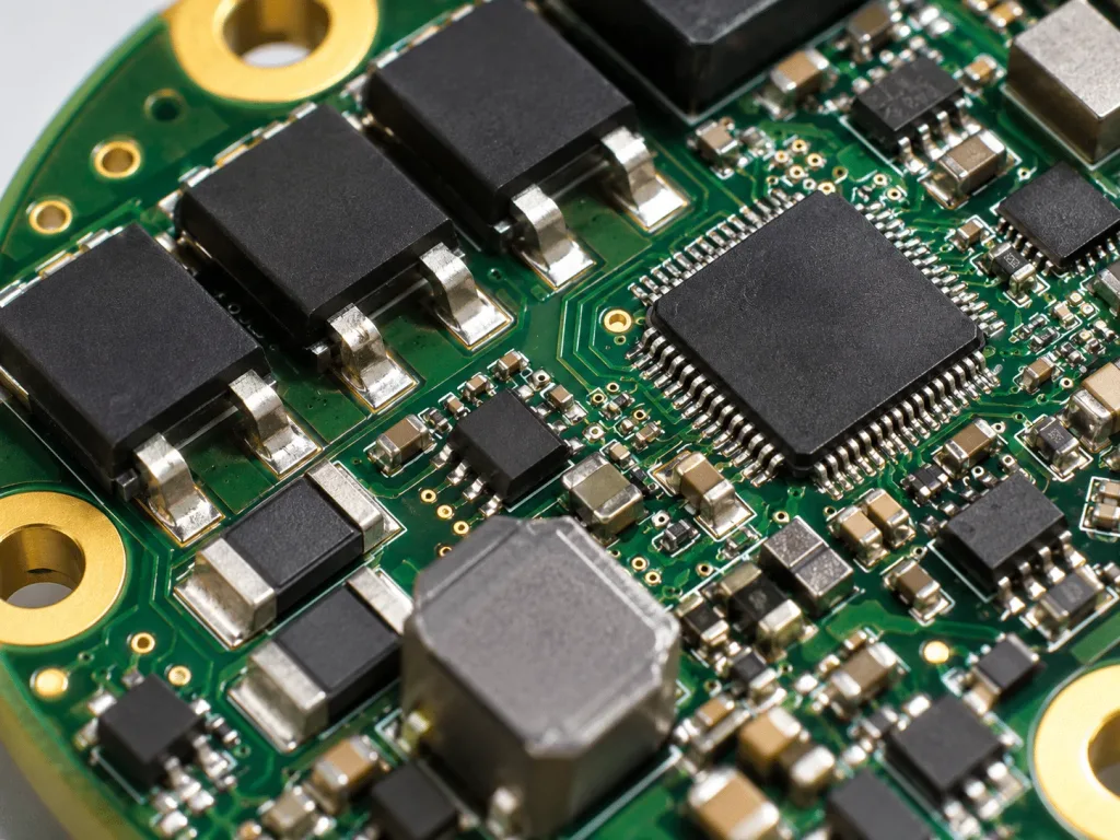
A joint motor driver board controls current delivered to an actuator motor. Depending on the motor and power stage, it may carry gate drivers, power MOSFETs, current sensors, a microcontroller, and communication circuits. Some actuators place these functions on one compact board; others separate power and control sections.
An encoder board measures motor or joint position. It may use magnetic, inductive, or optical sensing and send feedback to the control system. Encoder signals need stable power, suitable grounding, and protection from switching noise generated by the motor drive.
The PCB must also fit the joint housing. Circular outlines, mounting holes, connector angles, and component height can be as important as the number of layers.
Hand and Tactile Sensor Boards
A dexterous hand may contain small motor controls, finger position sensors, force sensors, and tactile sensing circuits. The available space is limited, especially inside the fingers.
Some designs place small rigid boards near the sensors. Others use flexible circuits to route signals through narrow spaces or connect moving sections. Fine-pitch assembly and sensor placement need attention because even a small placement change can affect mechanical fit.
Onboard Compute and Communication Boards
The robot’s compute system processes camera, sensor, and motion data. A carrier PCB may connect a compute module to memory, cameras, Ethernet, and other interfaces. The carrier is not always the processor board itself.
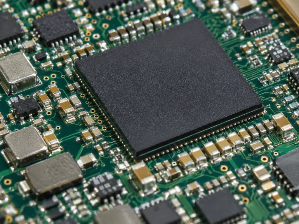
These boards can require multilayer routing, controlled impedance, dense connectors, and BGA assembly. Their thermal design also depends on the compute module and its connection to the chassis or cooling system.
Power Distribution and Battery Management Boards
Power distribution boards deliver energy from the battery system to joint drives, processors, and auxiliary circuits. Battery management boards may monitor cell voltages, current, and temperature and control specified protection functions. Their exact functions depend on the battery architecture.
A robot may combine some of these functions or keep them on separate assemblies. High-current paths, protection devices, connector ratings, isolation needs, and heat removal should be reviewed for each board.
Flex and Rigid-Flex Interconnects
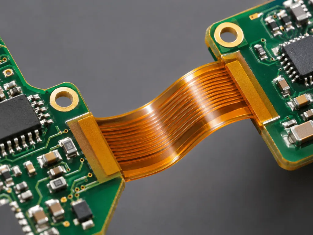
Moving joints need reliable paths for signals and sometimes power. Designers may choose a wire harness, flat flexible cable, flex PCB, or rigid-flex assembly according to the movement and electrical requirements.
A flex circuit that survives installation is not necessarily suitable for repeated motion. Its copper construction, layer count, bend radius, bend direction, and strain relief must match the expected movement. Torsion and bending need separate consideration.
How Are Humanoid Robot PCBs Different from Industrial Robot PCBs?
Humanoid and industrial robots share motor control, sensing, power, and communication technologies. The difference is the system packaging and the way the boards are distributed through moving mechanical structures.
A fixed industrial robot controller may sit in a cabinet with more space for cooling and connectors. A humanoid joint board may sit beside the motor inside a compact actuator assembly that moves with the joint. That location changes the board’s mechanical and thermal constraints.
Design factor
Conventional industrial robot installation
Humanoid robot installation
Board placement
Often uses cabinet or larger controller modules
Often distributes small boards near joints and sensors
Mechanical space
May allow larger boards and connectors
Can require tight outlines, low height, and low mass
Motion exposure
Moving harnesses and actuators, with many fixed control boards
Many boards and connections close to moving joints
Power and noise
Motor drive noise and high current remain important
Must also fit power and sensitive feedback circuits into smaller volumes
Interconnects
Cable harnesses and industrial connectors are common
May use harnesses, FPC, or rigid-flex in restricted routes
These are design tendencies, not rules for every robot. A humanoid compute board may be large and rigid. An industrial robot can also use compact or flexible electronics.
The practical supplier question is whether each board meets its actual space, movement, current, and inspection requirements.
PCB Manufacturing Requirements for Humanoid Robot Electronics
A single humanoid robot program may include ordinary multilayer FR-4 boards, high-density boards, high-current boards, and flexible constructions. We recommend preparing separate fabrication specifications for each board number rather than applying one set of limits to the complete program.
Multilayer and HDI PCB Requirements
Multilayer PCBs provide routing space and reference planes for control, sensor, and compute signals. The layer count should follow the component layout, return paths, interfaces, and available board area.
HDI becomes useful when fine-pitch components leave too little room for conventional fanout or through-hole vias. Microvias and via-in-pad may support a smaller layout, but they add fabrication steps and inspection considerations.
A compute carrier with a dense BGA may need different routing rules from a simple encoder board. Do not assume that every humanoid PCB requires HDI. Confirm the package pitch, escape routing, stackup, and finished board thickness first.
Heavy Copper and High-Current PCB Design
Motor drivers and power distribution boards may carry substantial current. The required copper cross-section depends on continuous and peak current, conductor geometry, acceptable temperature rise, duty cycle, and cooling conditions. Copper weight alone does not establish current capacity; calculations should consider IPC-2152 guidance where applicable and be checked against the product’s thermal conditions.
High-current design also requires attention to vias, plane transitions, and connector contacts. A wide surface trace will not solve a current bottleneck through a small via array or an undersized terminal.
Power devices need a defined thermal path. Copper planes, thermal vias, heat spreaders, and the mechanical housing may work together. The fabrication drawing should specify copper thickness by layer and finished board thickness. The design team must validate electrical and thermal performance under the intended operating conditions.
Flexible and Rigid-Flex PCB Requirements
Flex and rigid-flex boards can reduce connector count or help route circuits through constrained areas. They are useful when the mechanical layout supports their use, not simply because the product moves.
For a dynamic bend, define the working bend radius, expected cycle count, motion frequency, bend direction, and any twisting motion. Use IPC-2223 design guidance where applicable, then validate the actual moving assembly. The bend region should avoid unsuitable component placement and abrupt transitions that concentrate strain.
Flexible-section thickness, copper type, coverlay, adhesive structure, stiffener placement, and rigid-to-flex transitions affect fatigue life. Stiffeners must not interfere with the intended dynamic bend region. A flex tail designed to bend once during installation should not be treated as a proven high-cycle joint interconnect.
Controlled Impedance and Signal Integrity
High-speed compute interfaces and some encoder or communication links need defined signal characteristics. Controlled impedance may be necessary for specified differential pairs or RF lines.
The fabrication notes should identify each controlled net group, target single-ended or differential impedance, tolerance, reference layer, and approved stackup. The layout must also preserve reference paths through connectors and layer transitions.
Motor switching can disturb nearby low-level sensor circuits. Grounding, filtering, physical separation, and cable routing need to be reviewed at the system level. Passing a PCB impedance-coupon test does not establish system-level EMC compliance or freedom from motor interference.
PCB Assembly Requirements for Humanoid Robot Boards
The same robot can require several assembly processes. A small encoder board, a BGA compute carrier, and a high-current driver PCB should not share one unqualified assembly plan.
Fine-Pitch SMT and BGA Assembly
Compact control and compute boards may use QFN, BGA, fine-pitch connectors, and small passive components. Accurate footprints, solder paste openings, and component orientation are essential.
BGA joints are hidden under the package. X-ray inspection can help assess suitable hidden solder features, but it does not replace electrical and functional tests. The assembly plan should also define moisture-sensitive component handling and compatible reflow requirements.
Power Component and Connector Assembly
Driver and power boards may use large MOSFET packages, inductors, bus connectors, through-hole parts, or mechanical hardware. These parts place different demands on solder volume, heating, and mechanical support.
Connector insertion forces and cable loads should not be carried by solder joints alone when the mechanical design requires additional support. We recommend reviewing heavy-component retention, mounting holes, and access for inspection before production release.
Flex and Rigid-Flex PCB Assembly
Flexible sections can deform during stencil printing and placement. Assembly fixtures or support panels may be needed to hold the rigid mounting areas in position.
Component placement should respect the intended bend zones. Stiffener positions, connector orientation, and post-assembly handling must match the drawing. Folding a rigid-flex assembly into its enclosure without a defined sequence can damage copper or solder joints.
Inspection and Testing for Humanoid Robot PCBAs
Inspection plans should be chosen by board function and package risk. A single inspection method cannot validate power handling, encoder accuracy, and moving-interconnect life.
AOI, X-ray, and Electrical Testing
AOI can check visible assembly features such as missing parts, polarity, and certain solder defects. X-ray can support inspection of hidden joints, including BGA connections where the package and image quality permit useful evaluation.
Bare-board electrical tests check specified conductor connections before assembly. On assembled boards, ICT, flying probe, or other electrical checks may be appropriate according to access and volume. Choose the electrical test strategy before finalizing test-point access and the production panel.
Functional Testing for Different Board Types
A joint driver test may check supply rails, gate-drive signals, current-sense measurements, encoder communication, and specified protection responses. A powered motor test requires an agreed fixture, supply limits, load condition, and safe operating procedure.
A sensor board may need a reference stimulus and acceptance limits for its output. A compute carrier may require power sequencing and interface checks. A power distribution or BMS board may require continuity checks, protection-response testing, and voltage-drop or current-sense verification under specified conditions.
These tests require customer-approved procedures and pass limits. Passing a PCBA test does not confirm whole-robot motion safety or performance.
Mechanical and Reliability Considerations
Vibration, shock, temperature change, connector retention, and repeated flexing can affect electronics in a moving robot. The relevant tests depend on installation position and product requirements.
Dynamic flex life cannot be inferred from a generic flex PCB specification. Validation should reproduce the expected bend radius, cycle rate, twisting, mounting, and environmental conditions as closely as practical. A cable or FPC that passes a static continuity check may still fail under repeated motion.
How to Evaluate a Humanoid Robot PCB and PCBA Supplier
The first supplier check is not whether the factory advertises robotics experience. It is whether the supplier can review the actual board set and explain which processes, materials, assembly steps, and tests apply to each item.
We recommend asking for a board-by-board manufacturing review. That review should cover the rigid, HDI, high-current, and flex or rigid-flex designs in the project without combining their separate process limits into one unrealistic specification.
A useful supplier review should answer these questions:
Can the factory fabricate the specified stackup, minimum features, copper weights, and board thickness for each design?
Can it build the required flex and rigid-flex constructions, including stiffeners and controlled bend areas?
Can it assemble the selected fine-pitch packages, connectors, and power components?
Which inspection steps are included, and which functional tests require customer fixtures or software?
How will BOM changes, alternative components, and PCB revisions be approved?
Can it maintain separate part numbers, production records, and acceptance criteria across the complete board set?
One supplier handling fabrication and assembly can reduce handoff work, but the scope still needs to be clear. Firmware, motor calibration, flex-life validation, and whole-robot testing should not be assumed to be included in PCBA production.
Ask the supplier to identify open engineering questions before pricing the full build. A clear list of missing data prevents quotations from relying on assumed stackups, component substitutions, or undefined tests.
What Files Are Needed for Humanoid Robot PCB Manufacturing and Assembly?
Multi-board projects need one controlled release package for each board, plus a project-level list that links the assemblies together. Mixing revisions between joint drivers, sensor boards, and carriers can create fit or communication problems.
PCB Fabrication Data
For each bare board, prepare the approved Gerber or ODB++ data, NC drill files, fabrication drawing, dimensions, and stackup. Include the finished thickness, copper weights, surface finish, impedance requirements, and special features when applicable.
Flex and rigid-flex drawings also need rigid and flexible region boundaries, stiffeners, coverlay openings, and bend requirements. Controlled impedance and mechanical requirements should be stated as specifications, not left for the factory to infer from layout artwork.
Assembly and Component Data
Each PCBA needs a BOM with manufacturer part numbers, quantity per board, and approved alternatives. Include pick-and-place data, assembly drawings, polarity notes, and special handling instructions.
Provide programming data and test instructions when those operations are requested. Identify any supplied components, long-lead items, and parts that require special storage or assembly handling.
Multi-Board Project Documentation
A project-level board matrix should link every PCB and PCBA part number to its revision, quantity, placement in the robot, and test plan. It should also record which boards share connectors or mating interfaces.
Keep mechanical drawings and interface requirements with the appropriate revisions. If a connector, cable, or enclosure changes, review the affected boards and mating interfaces before releasing a new production build.
Matching PCB Manufacturing Capabilities to Humanoid Robot Board Requirements
A humanoid robot PCB supplier should be evaluated against the actual board mix, not against a generic claim about making robot electronics.
Multilayer or HDI as required, BGA assembly, impedance control
BGA fanout review, stackup, inspection plan
Power distribution and BMS
Copper and connector requirements, protection assembly
Current-path drawing, BOM, electrical test limits
Joint-crossing interconnect
Flex or rigid-flex build, strain relief, defined bend zones
Bend drawing, material build, validation conditions
A production release should address the unresolved risks of each board, starting with those that have the greatest potential impact. A proven rigid controller does not validate a dynamic flex interconnect, and a passed solder inspection does not validate a high-current thermal path.
Before approving a production order, compare each board’s fabrication drawing, assembly data, and test criteria against the supplier’s documented process plan. This gives the engineering and purchasing teams a clearer basis for accepting a multi-board build.
Engineering Support for Your PCB Project
Need help with your PCB or assembly project? Contact our team to discuss your design, manufacturing and testing requirements.
Inconsistent solder paste deposits on fine-pitch HDI pads can result from poor paste release from the stencil, uneven board support, problems with paste storage or handling, or incorrect printer settings. The HDI
PCB board technology is how modern electronics get both mechanical support and copper interconnects on a single laminate—pads, traces, vias, layers, and materials that determine density, speed, heat, and cost. By the
The cost of a 10-layer rigid PCB depends on its size, materials, copper weight, hole structure, and manufacturing requirements. Order quantity, testing, and delivery timing also affect the quote. Two boards with
To provide the best experiences, we use technologies like cookies to store and/or access device information. Consenting to these technologies will allow us to process data such as browsing behavior or unique IDs on this site. Not consenting or withdrawing consent, may adversely affect certain features and functions.
Functional
Always active
The technical storage or access is strictly necessary for the legitimate purpose of enabling the use of a specific service explicitly requested by the subscriber or user, or for the sole purpose of carrying out the transmission of a communication over an electronic communications network.
Preferences
The technical storage or access is necessary for the legitimate purpose of storing preferences that are not requested by the subscriber or user.
Statistics
The technical storage or access that is used exclusively for statistical purposes.The technical storage or access that is used exclusively for anonymous statistical purposes. Without a subpoena, voluntary compliance on the part of your Internet Service Provider, or additional records from a third party, information stored or retrieved for this purpose alone cannot usually be used to identify you.
Marketing
The technical storage or access is required to create user profiles to send advertising, or to track the user on a website or across several websites for similar marketing purposes.
 Skip to content