 Skip to content


PCBs and Assemblies for Security Equipment
Topline Circuit provides PCB fabrication and assembly for surveillance cameras, access controllers, alarm panels and security gateways. Share the board revision, order quantity and installation conditions so we can review the construction and test scope for your quote.
Manufacturing Requirements by Application
| Application | What to specify | What we review |
|---|---|---|
| IP cameras and recorders | Image sensor interface, Ethernet interface and Power over Ethernet (PoE) requirements, if applicable, connector positions and enclosure clearances. | Stack-up, specified impedance, mechanical fit and access for functional testing. |
| Access controllers and smart locks | Reader interface, supply range, relay or lock load and behavior during power loss. | Connector fit, current paths and the fixture needed to test switching and recovery. |
| Alarm panels and sensors | Input states, thresholds, backup power and expected alarm responses. | Test access, input simulation and output checks. |
| Security gateways and intercoms | Network or audio interfaces, firmware and device ID requirements. | Assembly fit, programming access and communication tests. |
Review Camera Interfaces and Installation Conditions
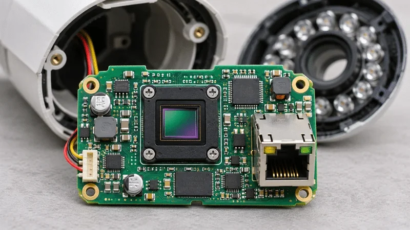
Provide the connector locations, board outline, mounting drawing and any specified impedance targets and tolerances. For outdoor or enclosed equipment, include the operating temperature range, cooling conditions and any coating and masking requirements.
For PoE cameras, specify the applicable PoE standard and power class, the switch or injector, and the cable type and length for testing. Define how quickly the board must start streaming and how long the stream must remain stable.
Define Power, Relay and Alarm Tests
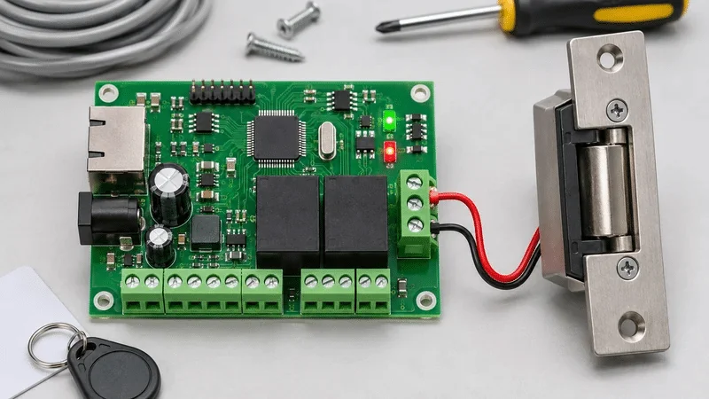
Specify supply limits, load type, steady-state and peak current, and how long the load stays on. For relay or lock outputs, provide the load or simulator and describe the expected output state during normal operation, power loss and recovery.
For alarm inputs, provide the states or thresholds to simulate, the expected output and the maximum response time. Identify which checks apply to each unit or to a sample.
Record Firmware and Test Results
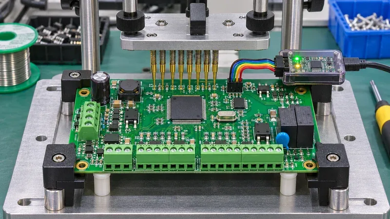
Provide the approved firmware, programming interface, device ID allocation and verification steps. Specify which records to link to the board serial number, such as firmware revision, test step, measured value, unit and pass/fail result.
For repeat builds, identify which component substitutions need approval and which tests must be repeated before release.
Files for a Security Equipment PCB Quote
- Released fabrication data, stack-up and fabrication drawing
- BOM, placement data and assembly drawings for PCBA orders
- Connector pinouts, installation drawing and applicable power or load requirements
- Build quantity, firmware, test procedure, acceptance limits and report requirements
See our PCB assembly services for sourcing and assembly options. Review our PCB testing and inspection services when defining the acceptance criteria.
Security Equipment PCB FAQs
Per-unit testing can be included once we agree on the setup and pass criteria. Send the PoE standard and class, switch or injector, cable length and firmware version. Set the maximum time to the first video stream and the minimum time it must run without dropping, and tell us whether to log results by board serial number.
Send the wiring diagram, load voltage, steady-state and inrush current, and whether the fixture should use the actual lock or a simulator. Specify the expected output state and switching time during normal operation, on power loss and after power returns.
Make a test matrix that pairs each input state with the expected alarm output and maximum response time. For a supervised loop, include the resistor values or resistance ranges for each applicable state, such as normal, alarm, open or short. Add the connector pinout so the fixture can reproduce each state.
Firmware programming can be included in the assembly order. If you need device ID traceability, send the approved firmware, programming interface and ID list or allocation rules. Specify how to read back the ID, handle duplicates and link the verified ID to the board serial number.
Provide the enclosure and mounting drawings, operating temperature and humidity requirements, and any coating and masking specifications. If your enclosure has an ingress protection target, include it as context and list the board-level checks required for this order. Mark connectors, sensors and other areas that must stay free of coating.
Yes. For bare boards, send the released fabrication data and quantity. For assemblies, also provide the BOM, placement data, assembly drawings and any programming or test requirements.
Discuss Your Security Equipment PCB Requirements
Send your board revision, quantity and application. Include interface, load and installation requirements, along with the tests and records needed for your quote.