 Skip to content


Custom Wire Harness Assembly
Specify the Harness as It Will Be Installed
Define how the harness connects boards, power supplies and enclosure interfaces. Send the branch drawing, wire list and estimated quantity so we can review fit, materials and testing for your build.
Show where each branch exits the main bundle, which way each connector faces and where the harness attaches to the enclosure.
Define Branch Lengths and Breakout Locations
Label the main trunk, each breakout and every connector on the layout. Dimension each branch from a named breakout reference to a defined endpoint, such as the connector mating face. Specify the tolerance, measurement path and harness condition separately. For example, state whether to measure along the branch centerline with the harness laid flat and without tension.
Show clip positions, grommets, sleeve ends and any service loops. Include enclosure drawings or photos of restricted areas so the sample can be checked against the installed route.

Harness Specification Checklist
| Item | What to specify |
|---|---|
| Layout | Trunk and branch lengths in mm, breakout references, measurement conditions and tolerances |
| Wire list | Wire ID, source and destination connector IDs and cavities, wire size (AWG or conductor cross-sectional area in mm²), insulation and color |
| Connectors and terminals | Manufacturer part numbers, mating-face or wire-entry view, keying, contacts, seals and cavity plugs |
| Splices and shields | Splice locations and circuits, shield and drain-wire endpoints, and specified protection |
| Installed fit | Connector orientation, clip and grommet positions, bend clearance, strain relief and label locations |
| Acceptance | Drawing revision, dimensional and electrical limits, sample or unit coverage and required reports |
Match the Wire List to the Physical Layout

Give every connector a unique ID, especially when several branches use the same housing. List each wire by origin and destination cavity, and mark splices, unused positions and any shield connections. Use the same IDs on the drawing, wire list, labels and test program.
Specify the termination and any crimp requirements for the selected wire and contact. Define the protection needed at breakouts, panel openings and locations where the harness may rub against the enclosure.
Approve a First Article in the Actual Installation
Check the sample against the released drawing and bill of materials. Use the intended enclosure and mating parts to check branch reach, latch access, clip engagement, bend clearance and strain near each connector.
Record approved changes before repeat production. Update the layout, wire list and test instructions together if a connector or branch changes.
Separate Wiring Checks from Fit and Strength Tests
Use the approved wire list to define checks for continuity, open circuits, shorts and miswiring. Verify shield continuity or isolation where specified, and agree on fixture connections and reporting before the build.
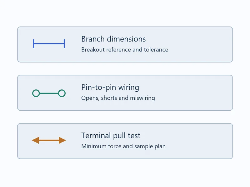
Check branch dimensions, orientation and labels separately. For a pull test, specify the method, minimum force (N) and sampling plan. For insulation resistance, specify the circuits, test voltage (V), duration (s) and minimum resistance (MΩ). For dielectric withstand, specify the circuits, AC or DC test voltage (V), duration (s) and pass criteria.
Files for a Wire Harness Quote
- Dimensioned branch layout and revision
- From-to wire list and bill of materials, including mating parts
- Installation photos or enclosure drawing, with fixing points and clearance restrictions
- Quantity, packaging, first-article requirements and acceptance tests
If the harness will connect to a board we build, include the mating connector and routing constraints in your PCB assembly requirements.
Wire Harness Assembly FAQs
Yes. Send photos of the full harness laid out and of each connector, plus the intended quantity and installation details. Label the ends and identify any damaged or modified areas. Use the sample to confirm dimensions and wiring, then approve the drawing and wire list before production.
Mark the breakout reference and endpoint on the drawing, such as the edge of the sleeve and the connector mating face. State whether to follow the branch centerline, how the harness should be positioned, and the allowed tolerance. Use that same method on the first article.
Assign each connector a unique ID and mark its branch and mating location. Specify a visible label or approved keying difference where needed, then check each label against the mating location during trial fit and verify the cavity map against the approved wire list.
Continuity verifies electrical paths. It does not check branch reach, latch access or strain. Trial-fit the sample with the actual enclosure, clips and mating connectors. If a branch is too short or puts tension on a terminal, record the affected branch and the fit or strain issue. Update the drawing and verify a revised sample before approving the build.
Specify pull testing when termination strength must be verified, and insulation resistance or dielectric withstand when the electrical requirements call for it. Define the method and limits for each test. Use designated samples for destructive pull testing. Specify whether each electrical test is performed on every harness or on a sample.
For a housing change, verify the actual mating part, keying and latch. For a terminal change, check housing compatibility, conductor size, insulation diameter and crimp tooling. Confirm electrical ratings for the proposed combination. Approve the updated bill of materials and sample before changing the production build.
Send Your Harness Drawing for Review
Share the branch layout, wire list, quantity and test requirements. Flag any dimensions, connector choices or installation details that still need confirmation.