 Skip to content


Solderable Edge Connections for PCB Modules
We manufacture half-hole PCBs, also called castellated PCBs, for modules and board-to-board solder connections. Our services cover prototypes and production, with fabrication review, profiling, inspection and assembly support.
Send the board outline, plated hole positions and assembly requirements. We review the edge connections, retained copper and panel support before confirming the manufacturing proposal.
Define the Plated Holes and Finished Board Edge
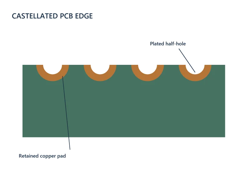
Castellations are plated holes that are partially opened by the finished board profile. The exposed plated wall and associated pads provide a solderable connection at the edge.
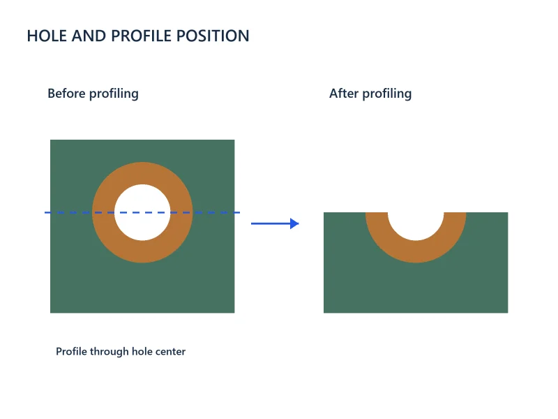
Show the intended profile relative to each hole. For a nominal half-hole, the profile passes through the hole center; other retained shapes need an explicit drawing and manufacturing review.
Specify the Edge Feature You Need
Different edge features need different manufacturing instructions.
Plated Half-Holes
Partially opened plated holes provide individual electrical connections along the module edge. Identify the associated pads, nets and required finished profile.
Continuous Edge Plating
A continuous plated board edge is a different feature from a row of castellated holes. Define the edge length, connected copper and any areas that must remain unplated.
Unplated Edge Notches
An unplated notch provides a mechanical shape without a plated electrical connection. Mark plated and non-plated features separately in the fabrication data.
Review Hole, Pad and Profile Dimensions Together
A minimum hole diameter alone does not define a manufacturable castellation.
Hole Diameter and Pitch
Specify the plated hole diameter before profiling, its tolerance and the center-to-center pitch. Identify any required remaining opening after profiling separately. We review these dimensions with the board thickness and material.
Retained Pad and Copper
Define the top and bottom lands and the copper retained inside the finished outline. Check nearby traces, pads, inner-layer clearances and the mechanical strength of the edge features.
Profile Position and Tolerance
Show how the board edge intersects each plated hole. Agree on the profile tolerance and permitted variation in the remaining connection geometry.
Surface Finish and Mask
Choose the finish for the soldering process and storage requirements. Define the soldermask openings and nearby mask bridges for the module and host-board interface.
Plan Panel Support Around the Castellated Edges
Castellated edges need a panel and profiling plan that keeps the board supported while the functional edges are formed. Identify which edges contain electrical connections and where support tabs can be placed.
Keep support and depanelization features away from functional castellations wherever the construction permits. Designs with castellations on all four sides or inside a cutout need an early review of tool access and support.
Manufacturing Controls for Clean Edge Connections
We review the process sequence for the actual board rather than treating castellations as ordinary edge vias.
Hole Metallization
Form the specified plated connections and inspect relevant hole and pad geometry. Maintain the required connection between the plated wall and retained copper.
Profiling and Copper Retention
Select the profiling route and support to control burrs, copper tearing and lifted plating. Review small holes and fine pitch together with tool access and the amount of material that remains after routing.
Finish and Final Inspection
Check the finished profile, plated surfaces, burrs and cleanliness against the agreed requirements. Include electrical testing and any required dimensional or inspection records in the order.
Match the Module to the Host Board
Provide the module land pattern and the matching host-board footprint when assembly is included. Review pad overlap, board alignment, soldermask and paste requirements together.
The solder joint depends on both boards and the assembly process. Confirm the finish, soldering method and inspection criteria before production, including any mechanical loading requirements for the assembled module.

What Affects Cost and Delivery?
The quotation reflects the complete edge construction and order scope.
Geometry and Material
Hole size, pitch, board thickness, materials and profile tolerances affect the manufacturing route. Review the smallest features only where the design needs them.
Panel and Process
Functional edges, support locations, extra profiling work and inspection requirements affect production effort and panel utilization.
Order and Assembly Scope
Provide quantities, target delivery date and whether the order includes module assembly or attachment to a host board. We review the files and material supply before confirming the schedule.
Files for a Half-Hole PCB Quote
Send the available design package and clearly identify the castellated features.
- Gerber or ODB++ copper data and drill files
- Board outline and fabrication drawing showing each half-hole location
- Hole sizes, pitch, pad dimensions and profile tolerances
- Layer stack-up, materials, copper and finished board thickness
- Plated and non-plated edge features and relevant clearances
- Surface finish, soldermask requirements and proposed panel support
- Quantity, target date and required inspection records
- For assembly: BOM, placement data, module and host-board drawings
Our PCB DFM review checks the fabrication data before production. See our PCB assembly services if your project includes assembled modules.
Half-Hole PCB FAQs
Yes. Both terms describe plated holes partially opened at the board edge. Mark their positions and intended profile in the fabrication drawing. Continuous edge plating and unplated notches are different features and should be specified separately.
Yes, if the revised design meets the castellation requirements. Changing the outline alone is not enough; check the retained pads, hole geometry, connected copper, profile tolerance and panel support. Send the original files and intended edge so we can identify the fabrication and layout changes needed.
Specify the plated hole diameter before profiling and the center-to-center pitch; pitch is not the edge-to-edge gap. Include the board thickness, material, retained pad dimensions and final profile. We review the drilling, copper retention and routing access together before confirming the minimum dimensions for your construction.
Yes, when the panel and profiling route can support the construction. Send the outline, functional edge positions and any restrictions on support tabs. We review tool access, support and depanelization before you finalize the layout.
Send close-up images, the affected locations, hole and pad dimensions, and the fabrication revision. We review whether the feature is copper tearing, lifted plating, a burr or profile variation. Based on the drawing and agreed acceptance requirements, we confirm whether the boards are acceptable or need rework or replacement before assembly.
Provide the module and host-board footprints, board dimensions, required alignment and soldering process. For assembly, include the BOM, placement data, paste or stencil requirements and joint inspection criteria. We review both sides of the interface rather than the module edge alone.
Discuss Your Half-Hole PCB Project
Send your board files, castellated edge requirements and quantities. We will review the design and prepare a manufacturing quotation.