 Skip to content


PCBs and Assemblies for Connected Devices
Topline Circuit supports bare PCB fabrication and PCB assembly for wireless sensors, asset trackers, smart devices and industrial gateways. Share your board revision, build quantity and connectivity requirements so we can review fabrication, assembly, programming and testing for your quote.
Manufacturing Requirements by Application
| Application | What to specify | What we review |
|---|---|---|
| Battery-powered sensors | Supply range, sleep current limit and wake-up schedule. | Power measurement setup and access for programming. |
| Asset trackers | Radio bands, antenna type, enclosure and battery placement. | Antenna keepout, RF feed requirements and test access. |
| Smart devices | Board outline, connector locations, firmware and device ID format. | Assembly fit, programming interface and identification records. |
| Industrial gateways | Supply and interface requirements, radio configuration and operating conditions. | Connector fit, board construction and communication test setup. |
Review Antenna Placement and RF Test Access
Provide the wireless protocol and frequency bands, antenna or module part number, and the antenna keepout drawing. Show nearby batteries, cables and enclosure materials. If the design has a controlled-impedance RF feed, include the target impedance, tolerance and stack-up.
Define whether acceptance requires a conducted RF check at a test port or a radiated check with the intended enclosure. Specify the test channel, transmit mode, fixture or antenna setup, measured quantity and pass/fail limits with units.

Define Sleep Current and Transmit Checks
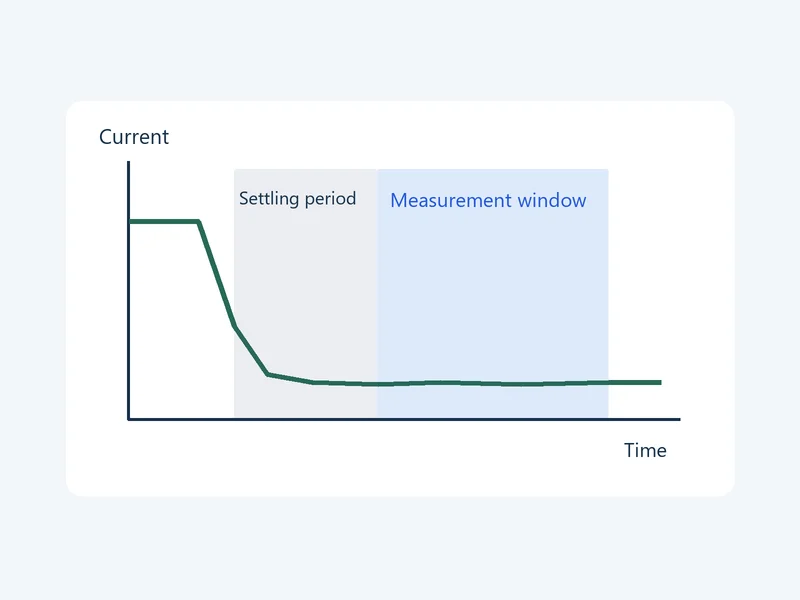
Specify the supply voltage, firmware revision, operating mode and sequence that puts the board into sleep. Specify how long to wait after entering sleep, how long to measure and the maximum allowed sleep current with units. State whether the limit applies to an average or a peak reading.
For transmit checks, specify the radio mode, output power setting, transmit duration, duty cycle and peak current limit. Indicate which checks apply to each board and which use sampling.
Program Firmware and Record Device IDs
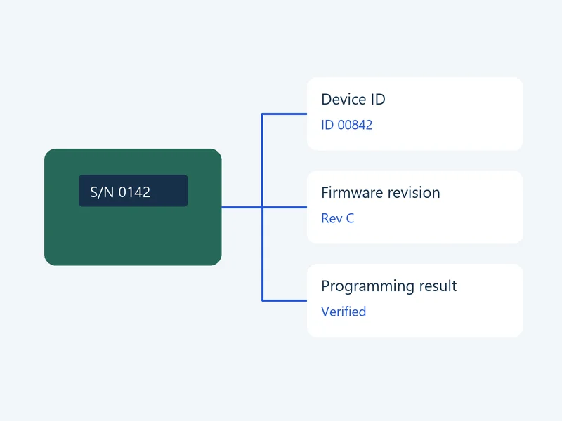
Provide the approved firmware file and version, programming interface and verification procedure. If each unit needs a unique identifier, specify the ID source, format, programming or labeling location, and duplicate handling.
Define which fields to link to the board serial number, such as device ID, firmware version, measured current and pass/fail result.
Files for an IoT PCB Quote
- Released PCB fabrication data, stack-up and drawings
- BOM, placement data and assembly drawings for PCBA orders
- Wireless module or antenna details, enclosure drawing and test access requirements
- Build quantities, firmware, test conditions, acceptance limits and reporting requirements
See our PCB assembly services for component sourcing and assembly options.
IoT PCB FAQs
Share the old and new mechanical drawings, antenna location and original RF test results. Flag changes to nearby materials or clearances. We use those details to agree on which checks to repeat with the revised enclosure and battery installed.
Request per-unit testing in your quote. Provide the supply voltage, firmware revision, steps to enter sleep, settling time, measurement window and current limit. Specify the current units and whether the limit applies to an average or a peak reading. Tell us whether to record the measured value, pass/fail status or both for each serial number.
Send the approved firmware and programming instructions, then specify where the IDs come from, how they are formatted and how to handle duplicates or failed programming. Specify the ID verification step and the report fields to link to each board serial number, such as the device ID, firmware version and programming result.
List the functions that must pass on the assembled board, such as startup, communication, sleep current or a defined RF check. Specify the setup and limits for each check and identify which results are required per unit.
Yes. Send the current board files and mechanical drawings. Mark tentative antenna, battery and enclosure dimensions. Identify which decisions are still open so we can confirm what can be quoted now and what needs review before production.
Yes. Send the released fabrication data for bare boards. For PCBA, add the BOM, placement file and assembly drawing, plus any programming and test requirements.
Discuss Your IoT PCB Requirements
Send your board revision, quantity and wireless application. Include the antenna and enclosure details, power requirements, and any programming or test records you need.