 Skip to content


Solderable Slots Matched to the Component
We manufacture PCBs with plated-through slots for flat component leads, connector tabs and other specified electrical connections. We support prototypes and production with fabrication review, slot machining, metallization, inspection and assembly.
Send the required finished slot dimensions, plated status and mating-part details. We review the opening, copper lands and manufacturing tolerances before confirming the production specification.
Specify Plated and Non-Plated Slots Separately
A plated-through slot has conductive copper on its internal walls and connects to the specified copper lands. A non-plated slot is a mechanical opening without that plated connection.
Identify the plated status in the manufacturing files and drawing. A slot shown only in the board profile does not provide enough information to establish the required plating.
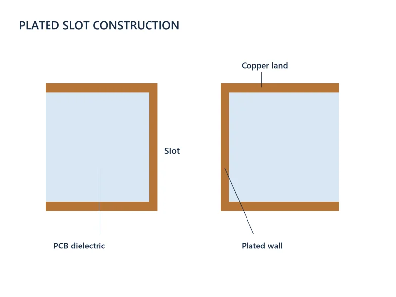
Define the Finished Slot Geometry
Use dimensions that describe the opening the component must fit after manufacturing.
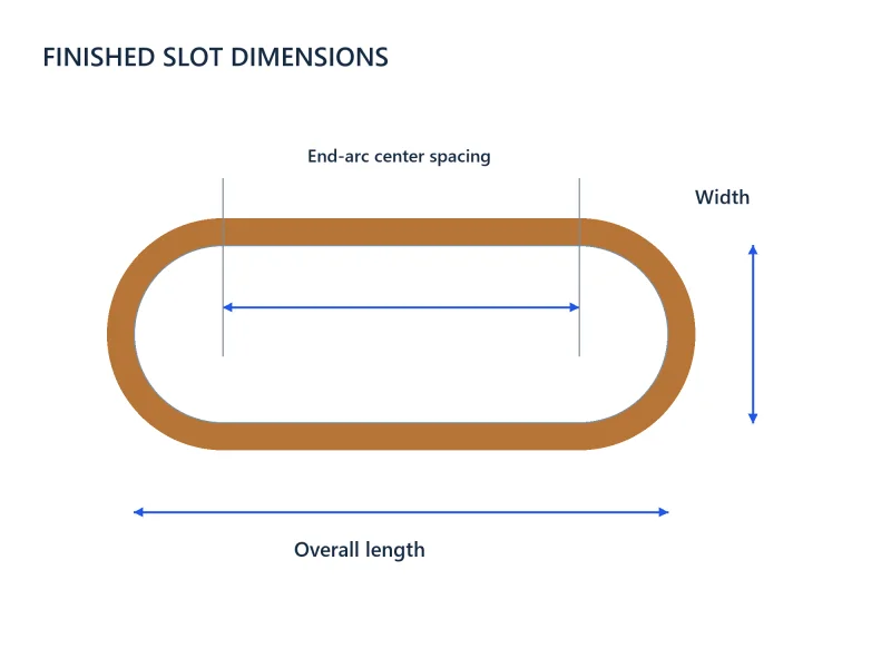
Finished Width
State the required opening after plating and surface finish, together with its tolerance. We select the machining allowance for the material, thickness, plating and process.
Overall Length
Dimension the total end-to-end slot length. Identify any CAD output that instead describes the travel between tool-center endpoints so it can be interpreted correctly.
End Radius and Shape
A round routing tool produces rounded ends. Provide the mating lead or tab drawing so we can check the complete envelope, including its corners, against the slot shape.
Position and Orientation
Locate each slot from the drawing datum and define its orientation. Include the position tolerance needed for connector alignment and assembly.
Keep Tool Dimensions Separate from the Finished Opening
The opening changes as copper and surface finish are deposited on the slot walls. A tool-size dimension and a finished-slot dimension are different requirements.
Specify the required finished width and length instead of adding an assumed plating allowance to the production data. We review tooling, process variation and plating distribution before agreeing on the manufacturing dimensions.
Review Copper Around the Entire Slot
Check the straight sides and rounded ends, not just the nominal slot center.
Copper Lands
Define the pad shape and retained copper around the slot. Review registration and copper margin with the actual machining geometry.
Internal Connections and Clearances
Identify which internal layers connect to the plated slot and which remain isolated. Check the clearance to internal planes and nearby copper features.
Board Thickness and Plating
Review slot width, board thickness, tool access and hole-wall preparation together. Specify the required plating and acceptance criteria for the selected construction.
Manufacture and Inspect the Plated Feature
The process sequence is selected to produce the specified electrical and mechanical connection.
Slot Formation
Form the slot using a suitable machining route before the metallization stages needed for wall plating. Review tool access, rounded ends and material support.
Wall Preparation and Copper Plating
Prepare the internal surfaces and deposit copper to connect the intended lands. Review the process with board thickness, slot geometry and the overall copper pattern.
Finished-Board Inspection
Check finished dimensions, location, visible defects and electrical connections against the order. Agree on any required plating measurements, microsections and inspection records.
Check the Flat Lead or Connector Tab Fit
Provide the mating-part dimensions, tolerances and assembly method. The finished slot must accommodate the lead envelope and the required insertion and soldering clearances.
Review the rounded slot ends, pad geometry, board thickness and insertion depth together. A nominal slot width greater than the tab thickness does not establish fit when the tab corners or length interfere with the opening.

Prepare Clear Slot Manufacturing Data
Use one consistent definition for each feature.
Slot Toolpath or Drill-Slot Record
Include slot data in a supported NC routing or drill-slot format, or provide an unambiguous dimensioned drawing for CAM review. Identify the file and layer containing each feature.
Plating Identification
Separate plated and non-plated features in the output or identify them explicitly in the drawing. Keep the copper lands, slot geometry and plating callouts consistent.
Avoid Conflicting Definitions
Remove duplicate or contradictory slot outlines from production files. A chain of overlapping round drills is not an automatic substitute for an approved slot toolpath; identify the intended feature for review.
Files for a Plated Slot PCB Quote
Send the available design package and identify the slot requirements that are fixed.
- Gerber or ODB++ copper layers and manufacturing drawing
- Drill-slot or routing data with plated and non-plated features identified
- Finished slot width, overall length, shape and tolerances
- Slot positions, orientation and drawing datums
- Pad geometry, internal connections and copper clearances
- Materials, stack-up, copper and finished board thickness
- Surface finish, quantity, target date and required inspection records
- Mating-part drawing and assembly files where fit or assembly is included
Our PCB DFM review checks the slot data with the rest of the board. See our PCB fabrication services for the wider manufacturing scope.
Plated Slot PCB FAQs
Identify the slot as plated in the manufacturing drawing and the supported drill or routing output. Include the associated copper lands and required internal connections. Do not rely on a line in the outline layer alone to communicate the plating requirement.
Yes. Specify the total finished length from one rounded end to the other. For a straight slot cut in one pass, the machined overall length equals the tool-center travel plus the tool diameter; plating then changes the opening. Label the dimension basis and provide the finished width and tolerances for CAM review.
Compare the measured opening with the specified finished size and the mating-part drawing. Check tab tolerances, rounded ends, position and whether the supplied dimensions describe the finished opening or the machining toolpath. Send measurements, photos and the two drawings so we can identify the interference and review the required correction.
Yes, when the revised pad, clearances and manufacturing route support the change. Send the mating-part dimensions and required finished opening. We review internal connections, nearby copper and slot orientation before the revised production files are approved.
Include a supported drill-slot or NC routing output and a dimensioned fabrication drawing. Identify units, file purpose and plated status. If the export represents the slot as a tool-center path or a contour, state which it uses and request a CAM review before production.
Not for a plated slot without considering the process. Copper and finish reduce the opening, while machining and plating variation affect the final size. Specify the required finished dimensions and tolerances; we determine the production allowance for the approved construction.
Discuss Your Plated Slot PCB Project
Send your board files, finished slot dimensions and quantities. We will review the manufacturing requirements and prepare a quotation.