 Skip to content


Submit Single-Board Files or an Existing Panel
Send your single-board files if you need help planning the assembly panel. If your boards are already panelized, send the panel drawing and matching production files so we can check handling, placement alignment and separation before assembly.
What to Specify on the Panel Drawing
| Feature | What to show |
|---|---|
| Finished panel and array | Overall length and width (mm), finished thickness (mm), rows and columns, board orientation and conveyor feed direction. |
| Process rails and edge clearance | Rail location and width (mm), component clearance from the conveyor edges (mm), and the location and dimensions of any overhang. |
| Fiducials and tooling holes | Fiducial coordinates, copper and solder mask opening diameters (mm). For required tooling holes, show coordinates, finished diameters (mm) and plating status. |
| Separation and delivery | V-score lines or routed paths, board spacing (mm) and tab locations. Mark sensitive edge features and state whether you need assembled panels or separated boards. |
Check Conveyor Clearance and Panel Support
Show which panel edges will run along the conveyor. Mark connector overhang, tall parts and underside components on the assembly drawing so we can review guide clearance and support on each assembly side.
For thin or flexible boards, include stiffener and support locations. We can review whether rails or a carrier suit the planned build.

Align Fiducials, Tooling Holes and Placement Data
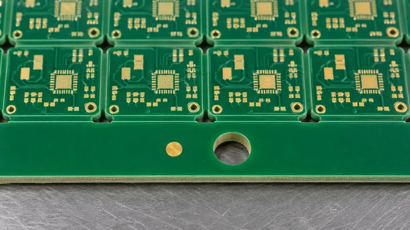
Keep panel fiducials visible to the placement camera and clear of conveyor guides and clamps. Identify any local fiducials needed near fine-pitch components and specify tooling holes where the fixture requires them.
State whether the pick-and-place file uses single-board or panel coordinates. Include the origin, units, rotation convention and assembly side so the placement data can be checked against the panel drawing.
Choose How the Boards Will Be Separated
V-scoring suits layouts with straight score paths and sufficient clearance along the cut. Tab routing can accommodate irregular outlines or areas where a continuous score line would cross another feature.
Mark components, copper and connectors close to the separation path. If edge finish or residual tabs matter to enclosure fit, specify the allowable edge condition on the drawing.

Files for an Assembly Panel Review
- Single-board Gerber or ODB++ data, drill files and board outline
- BOM, pick-and-place data and assembly drawings for the same board revision
- For an existing panel, include the panel drawing and matching panel data with the array, rails and separation features
- Required delivery format and any downstream fixture or enclosure constraints
See our PCB design for assembly review for placement and assembly checks and our PCB design for manufacturability review for fabrication checks.
Assembly Panel FAQs
Yes. Send the board data and outline, BOM, pick-and-place file and assembly drawing. Tell us whether you need assembled panels or separated boards so we can review the panel layout and delivery scope.
Send the panel drawing and matching production files for review. Include rail widths, fiducials, tooling holes, feed direction and the placement origin. Reuse depends on whether the panel fits the planned line and fixtures. If the panels are already fabricated, include a sample or photos with dimensions and identify any features that cannot be changed.
Mark its overhang, height, location and assembly side on the drawing. Show the proposed feed direction and any rail or tab beside it so we can review clearance and determine whether a different rail layout or carrier is needed.
Choose V-scoring when a continuous straight score path is available and nearby copper and components have enough clearance. For irregular outlines or interrupted paths, mark where routed tabs are allowed. If the board fits into an enclosure, specify how much tab material may remain after separation.
Single-board coordinates are enough for review when the array drawing identifies each board position and rotation. If you have a panel-level file, include its origin, units, rotation convention and assembly side, and check that it matches the panel revision.
Ready to Review Your Assembly Panel?
Send your board files or existing panel drawing, assembly data and delivery requirements. We will review the panel features that affect assembly and separation.