 Skip to content


PCBs and Assemblies for Drones and UAVs
Topline Circuit supports bare PCB fabrication and assembly for flight controllers, electronic speed controllers (ESCs), telemetry modules and gimbal interconnects. Share the board revision, quantity and installation constraints so we can review materials, assembly and testing for your quote.
Manufacturing Requirements by Board Type
| Board type | What to specify | What we review |
|---|---|---|
| Flight control and sensing | Board outline, mounting holes, weight limit, sensor interfaces and firmware. | Board fit, component clearance and startup test access. |
| ESC and power distribution | Supply range, continuous and peak current, peak duration, duty cycle and cooling. | Finished copper thickness, current paths and thermal constraints. |
| Telemetry and communications | Frequency bands, antenna placement, keepout and any specified impedance targets. | Stack-up, RF feed geometry and test access. |
| Gimbal and payload interconnects | Connector locations, travel range and minimum bend radius for moving flex. | Board fit, flex routing and stiffener placement. |
Review Weight, Mounting and Motion
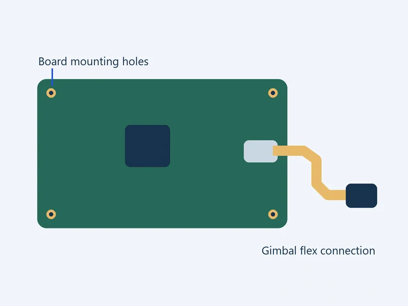
Provide a mounting drawing with the board outline, fastener locations, connector clearances and target weight. State whether the weight target applies to the bare PCB or the populated assembly. If vibration testing is required, provide the applicable profile, test axes, duration, mounting setup and acceptance criteria.
For moving flex, show the installed route through the full range of motion. Mark the minimum bend radius, expected cycle count and any twist angle. Show the clamp and stiffener locations.
Specify Current Paths and Cooling for ESC Boards

Mark the high-current paths and terminals on the schematic or layout. Provide the continuous and peak current for each path, peak duration, duty cycle, maximum ambient temperature and allowable temperature rise. Describe the available airflow or heatsink.
Include your proposed stack-up and finished copper thickness if specified. For a load test, provide the supply settings, load profile, test duration and pass/fail limits.
Plan RF and Functional Checks
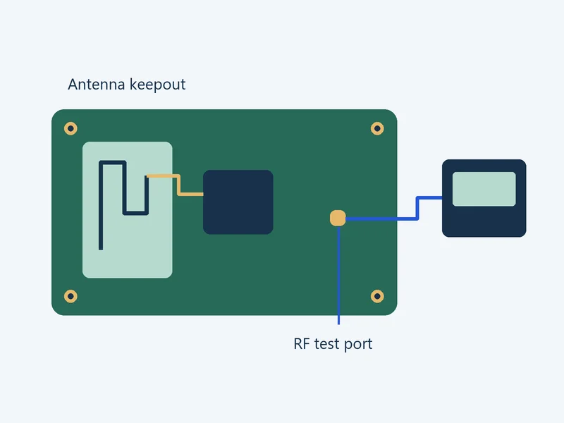
Send the antenna or module part number, frequency bands, antenna keepout and enclosure drawing. Include the RF feed impedance and tolerance where specified. If RF checks are required, specify the channel, enclosure configuration, measured quantity, units and acceptance limit. Identify whether the test uses a conducted connection or a radiated setup.
For startup, telemetry or drive-output checks, provide the firmware revision, pinout, inputs, loads and expected responses. Specify which checks apply to every unit and which results to record by serial number.
Files for a Drone PCB Quote
- Released fabrication data, drill files, stack-up and fabrication drawing
- BOM, placement data and assembly drawings for PCBA orders
- Mounting drawings, weight target and applicable thermal, motion or RF requirements
- Build quantities, firmware, test procedure, pass/fail limits and report requirements
See our PCB assembly services for sourcing and assembly options.
Drone PCB FAQs
Mark the current paths and give the continuous and peak current, peak duration, duty cycle, cooling conditions and allowable temperature rise. Include the proposed finished copper thickness and stack-up if available. We use these inputs to review the proposed construction and identify what needs confirmation before quoting.
Share the old and new mechanical drawings, antenna location and original RF test results. Mark changes to nearby materials and clearances so we can agree on the checks to repeat in the revised configuration.
Request per-unit testing in your quote. Provide the firmware revision, pinout, supply settings, inputs and load. Define the expected response and pass/fail limits, including units and timing where applicable. Specify which readings and results to link to each board serial number.
Send a drawing showing the flex route across the travel range. Mark the bend zones, minimum radius, expected cycles, twist and fastening points so we can review the proposed flex construction.
Send the current revision, prototype quantity, forecast production quantity and planned changes. Identify first article, material approval and test requirements for each stage. We review which materials, assembly processes and test setups can carry over to production.
Yes. Send the fabrication data for bare boards. For assemblies, add the BOM, placement data, assembly drawings and any sourcing, programming or testing requirements.
Discuss Your Drone PCB Requirements
Send the board revision, application and build quantity. Include mounting, weight, cooling or RF constraints and the tests you need for your quote.