 Skip to content


Check PCB Connectivity Before Assembly
Topline Circuit provides bare PCB electrical testing to check continuity within a net and isolation between separate nets. We compare the manufactured board with the approved connectivity reference before components are assembled.
Send your fabrication files, board revision, quantity and electrical test requirements. We review the reference data, test access, measurement limits and required records with your PCB manufacturing order.
Detect Opens and Unintended Connections
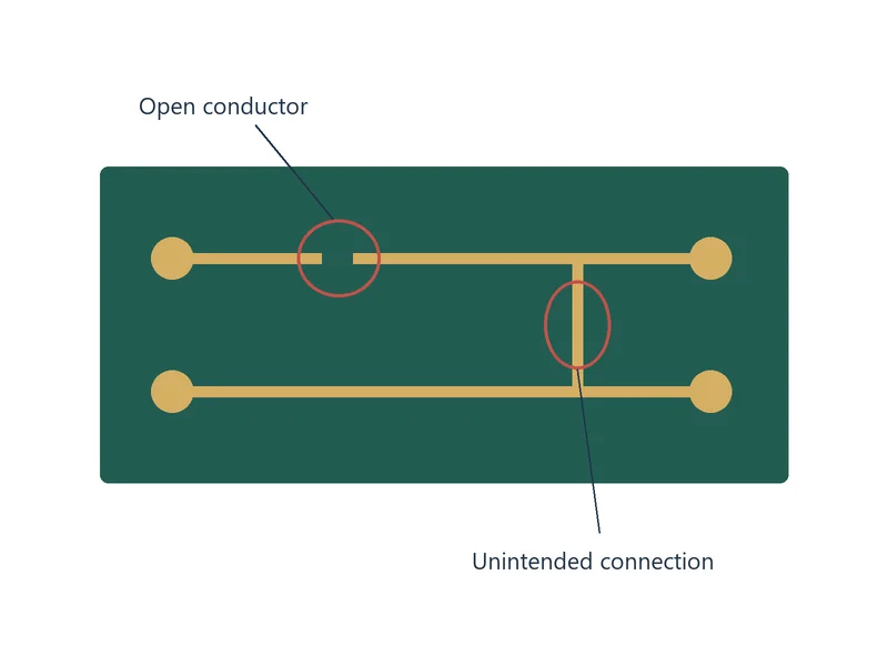
Continuity testing checks whether the required points within a net are connected within the specified resistance limit. It helps identify open conductors, broken connections and excessive resistance in the tested paths.
Isolation testing checks separation between different nets under the specified test conditions. It helps identify unintended connections and insulation resistance below the agreed limit.
Choose the Test Method for Your Build
| Method | How it contacts the board | Selection factors |
|---|---|---|
| Flying probe | Moving probes contact programmed locations without a dedicated bed-of-nails contact fixture. | Prototype quantities, design changes, available contact areas and the required test sequence. |
| Dedicated fixture | A board-specific contact arrangement connects the PCB to the tester. | Repeat production, design stability, contact count, cycle time and fixture preparation. |
Match the Test Reference to the Released Design

Provide consistent revision identifiers for the artwork, drill files and fabrication drawing. When available, include an independently exported design netlist in an agreed format, such as IPC-D-356, for comparison with the connectivity extracted from manufacturing data.
Identify net ties, intentional panel connections, embedded components and other special structures. Resolve differences between the design netlist and interpreted manufacturing data before approving the test reference.
Define the Electrical Test Requirements
| Requirement | Information to specify |
|---|---|
| Continuity limit | Maximum permitted resistance in ohms, applicable paths and the measurement method. |
| Isolation limit | Minimum permitted resistance in megohms or gigohms, applicable net pairs and test conditions. |
| Test voltage | The voltage required by the approved test procedure, with any specified duration and other conditions. |
| Tested quantity | Whether every delivered board or an agreed sample is to be tested. |
| Network coverage | Required networks, contact access, isolation-check strategy and any agreed exclusions. |
| Reference and records | Approved data revision, test program revision, product identification and required result format. |
Investigate Failures Before Retesting
Review the failed net or location against the approved test reference. Check probe contact, alignment and the physical board to distinguish a contact-related indication from a confirmed board defect or data mismatch.
Hold confirmed nonconforming boards for the agreed action. If repair is permitted, obtain the required authorization, verify the repaired area and repeat the applicable electrical tests before release.

Keep Test Results Traceable
Request the record detail needed for receiving inspection or engineering review: board or lot identity, product revision, test method, program revision, applicable limits and results.
Include failed-net findings, authorized repair and retest history where required. Agree on record format and delivery before production so that the result can be traced to the delivered board configuration.
Files for an Electrical Test Review
- Gerber or ODB++ manufacturing data and NC drill files
- Fabrication drawing, stack-up and approved board revision
- Independent design netlist, when available
- Board quantity and panel or individual-board delivery requirements
- Continuity and isolation limits, test voltage and applicable procedure
- Required test coverage, reports and traceability information
Coordinate electrical testing with our PCB fabrication services. For impedance measurements, assembly inspection or functional checks, see our testing and inspection overview.
Bare PCB Electrical Testing FAQs
Yes. Send the fabrication files you have so we can review test-data preparation. Connectivity can be extracted from the manufacturing data, but a separate design netlist provides an independent comparison with design intent. Identify any missing reference information before releasing the test program.
Identify the affected nets and compare the board revision, drill mapping, net ties and panel connections. Resolve which data represents the intended design and issue a consistent approved file set. Do not change the test reference simply to make a conflicting dataset pass.
Provide the quantity, expected repeat orders, design stability and available contact points. We compare programming, contact access, fixture preparation and test-cycle requirements for equivalent electrical coverage. Quantity alone does not determine the best method.
Send the fabrication drawing, applicable customer specification and application requirements. We review the missing limits and test conditions before production. Keep continuity resistance, isolation resistance and test voltage separate; the normal operating voltage is not automatically the correct test voltage.
No. The result covers the programmed continuity and isolation checks under the agreed conditions. Specify controlled-impedance measurements separately. To verify an assembled product, provide the required electrical or functional test procedure, including its operating conditions and pass/fail limits.
Review the failed location, probe contact and approved reference first. Hold boards with confirmed defects and agree on repair or replacement. Where repair is authorized, inspect the affected area and repeat the applicable tests before release. Request the original finding and retest outcome in the agreed records.
Discuss Your PCB Electrical Test Requirements
Send your board files, quantity and required test records. We will review the reference data, test method and electrical limits with your fabrication requirements.