 Skip to content


Selective Soldering Services
Solder Selected Through-Hole Joints on Mixed Assemblies
We provide selective soldering for PCB assemblies that need localized solder application to specified through-hole joints. We review the joint layout, solder-side components and thermal requirements to plan the nozzle path and process.
Send your board files, BOM and assembly drawing with the target joints marked. We will review access, support, materials and acceptance requirements before preparing the production program.
Review Access Around Each Target Joint
Identify the joints to solder and provide the position and height of nearby underside components. Review the nozzle approach, travel path, lead protrusion and clearance from components, tooling and board supports.
Include the finished plated-hole dimensions, lead geometry and tolerances for critical parts. A nozzle must reach the joint while maintaining the required solder flow and clearance throughout its path.

Choose the Soldering Route for Your Board
| Route | Useful project conditions | Review before selection |
|---|---|---|
| Selective soldering | Specified through-hole joints on a mixed-technology assembly | Nozzle access, local fluxing, thermal demand, program and tooling |
| Wave soldering | Groups of accessible solder-side joints suited to the process | Exposed components, pallet or masking needs and production quantity |
| Hand soldering | Individually accessible joints or operations requiring a defined manual method | Operator access, component limits, work instructions and inspection |
Plan Fluxing, Preheat and Solder Contact Together
Select a flux and solder alloy compatible with the PCB finish, component terminations and cleanliness requirements. Define flux deposition and preheat conditions for the actual board rather than treating them as independent settings.
Review board thickness, copper distribution and high-thermal-mass parts alongside the component soldering limits. Establish solder temperature, contact time, travel and withdrawal conditions using process trials and measured temperatures on a representative assembly.
Protect Existing SMT Components and Support the Board
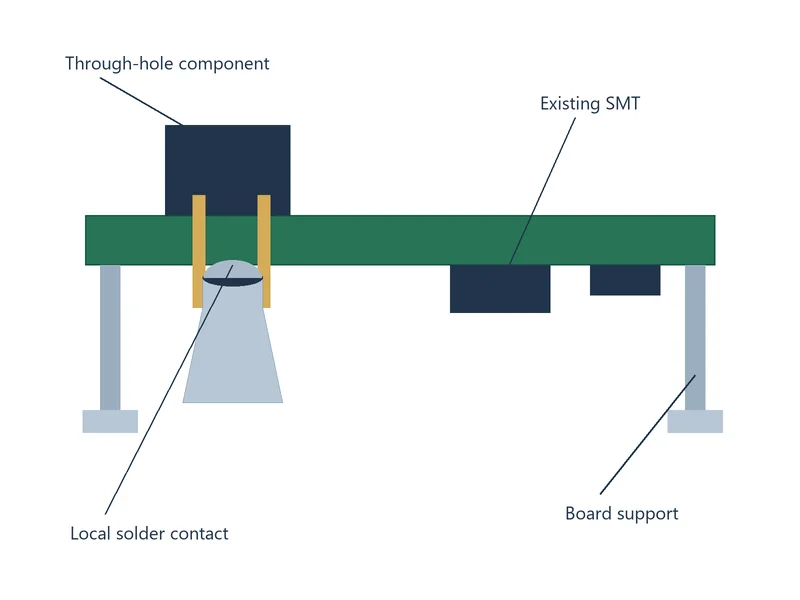
On mixed assemblies, review underside SMT locations, component heights and any heat-sensitive parts before selecting the nozzle and path. Local solder application reduces exposure elsewhere, but surrounding parts and the board can still receive heat during preheat and soldering.
Define the support and fixture arrangement to maintain a repeatable board position. Where shielding or dedicated tooling is needed, review its clearances and effect on access and heat transfer before approving the build.
Define the Inputs for Process Review
| Review item | Required information | Purpose |
|---|---|---|
| Target joints | Reference designators, pin locations and assembly drawing | Identify where flux and solder are required |
| Access geometry | Underside component positions and heights, lead protrusion and tooling clearances in mm | Check nozzle approach and travel |
| Hole and lead fit | Finished plated-hole and lead dimensions with tolerances | Review insertion and solder-flow geometry |
| Thermal demand | Board thickness, copper distribution, component limits and prior thermal exposure | Develop the preheat and soldering process |
| Materials | Approved alloy, flux, board finish and cleaning restrictions | Confirm compatibility and residue requirements |
| Process settings | Approved temperature limits in °C, contact times in s and travel speeds in mm/s, where applicable | Document the validated process window and machine program |
| Production control | Board revision, panel layout, fixtures and first-article approval | Release a repeatable program and setup |
| Acceptance | Applicable documents, revisions, class, test scope and records | Define joint inspection and release criteria |
Approve the Setup and Inspect the Soldered Joints
Confirm board location, fixture support, flux application and the soldering program on the initial build. Record the approved setup and any first-article hold point before releasing repeat production.
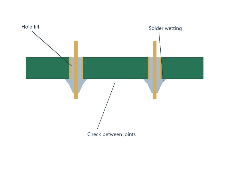
Inspect wetting, bridging, hole fill, lead condition and component damage against the specified acceptance criteria. Keep electrical and functional testing separate from joint inspection, with the required access, procedure and pass/fail limits.
Files for a Selective Soldering Quote
- PCB fabrication and assembly files with the approved board revision
- BOM and marked drawing identifying the joints to solder
- Top and bottom component positions, package dimensions and heights
- Board or panel dimensions, rails, fiducials and support requirements
- Critical finished-hole dimensions, lead geometry and protrusion
- Board thickness, copper information and component soldering limits
- Required alloy, flux, cleaning and inspection requirements
- Build quantity, first-article approval, testing and reporting scope
Selective soldering can form part of your PCB assembly order, alongside SMT assembly. Mark any unresolved access or thermal restrictions so they can be reviewed before process approval.
Selective Soldering FAQs
Yes, where the actual layout provides suitable access. Send the underside placement, component heights, target joints and lead protrusion so the nozzle path and tooling can be reviewed.
Check both physical clearance and thermal limits. If access is unsuitable, evaluate a different nozzle, tooling arrangement or approved soldering route before production.
Compare setup and tooling with the build quantity, repeat-order plan, joint access and component limits. Hand soldering may suit some small jobs, while a programmed selective process may be useful for repeat production. For a useful comparison, provide the board quantity, number of joints, connector part numbers and inspection scope. Compare initial setup and recurring assembly costs for the same requirements.
Confirm the obstruction using the approved layout, actual component heights and proposed nozzle geometry. Review another nozzle, a revised support fixture or a different qualified soldering method.
If a design change is needed, obtain approval for the revised component or board layout. Do not remove, move or modify parts merely to create access without an approved change.
Hold affected assemblies and record the joint locations and observed defects. Review solderability, finished plated-hole dimensions, lead fit, flux deposition and the measured thermal response against the approved process. Compare the result with the specified hole-fill criteria before classifying the joint.
Evaluate corrections within the board and component limits, then inspect the trial joints before releasing the change. Increasing temperature or contact time without that review can create other defects or damage.
Provide the exact part number and manufacturer soldering limits, including any restrictions on preheat and solder contact. Review the proposed path, solder contact time, shielding and surrounding thermal conditions. Confirm a suitable process on a representative assembly, or select another approved route if the component limits cannot be met.
State the required workmanship documents, revisions, class and customer criteria. Define inspection for wetting, bridging, hole fill, lead condition and component damage, with first-article records where needed.
Specify electrical or functional tests separately. For a failed joint or retest, retain the original result, document the approved correction and repeat the affected inspection and tests before release.
Review Your Through-Hole Soldering Requirements
Send your assembly files, target joints and component restrictions. We will review access, tooling, thermal requirements and inspection scope for your build.