 Skip to content


PCB DFM Check
Review Manufacturing Details Before Production
Our free design for manufacturability (DFM) review helps identify issues in your PCB production data before fabrication. We review the material, stack-up, layout features and fabrication notes together to identify manufacturing concerns.
Send your available files and the questions you need resolved. Our engineers explain any findings and discuss proposed changes with you. Changes to approved design data require your confirmation.
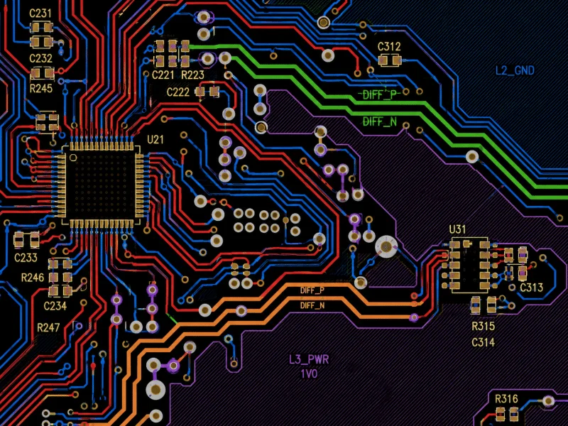
What We Check
The review follows your board construction and submitted files. We assess related features together, rather than apply one set of limits to every PCB.
Copper Features
Review trace widths, copper-to-copper clearances, narrow features and copper distribution against the layer position, finished copper thickness and intended process.
Drills and Vias
Check specified hole sizes and tolerances, annular rings, drill-to-copper spacing and via spans. Review blind, buried, filled and stacked structures against the proposed build-up.
Solder Mask and Silkscreen
Identify missing pad openings, narrow mask dams and markings that overlap exposed pads. Review mask and legend features against the manufacturing requirements.
Board Outline and Panelization
Check board-outline and drill-data consistency, copper-to-edge clearances, slots, cutouts and specified routing or V-score features. Include panel drawings when applicable.
Materials and Stack-Up
Review layer order, dielectric thicknesses, copper weights, finished thickness and material notes. Resolve conflicting specifications before fabrication.
Impedance Requirements
Review impedance targets, tolerances, reference planes and trace geometry against the stack-up. Confirm permitted adjustments and any coupon testing or reports.

Need Assembly Review as Well?
For PCB assembly, we also review how the board and components fit the planned assembly process. This design for assembly (DFA) review needs more than bare-board artwork.
- BOM part numbers, component footprints and placement-data consistency
- Component orientation and polarity instructions
- Component spacing, access and supported placement areas
- Soldering, carrier and handling requirements
- Programming interfaces and test-access requirements
Include the BOM, pick-and-place data and assembly drawings, plus relevant component datasheets and test instructions.
Feedback Your Team Can Act On
When we identify an issue, we explain what needs attention and the information needed to resolve it.
Locate the Issue
We identify the affected layer, feature, location or component reference so your team can locate the issue in the design.
Explain the Impact
We explain how the issue affects fabrication or assembly and identify the requirement that needs clarification.
Agree on a Resolution
We discuss a practical correction or request missing information. Your team approves design changes before we use the revised files for production.
Files for a DFM Check
Send one clearly labelled project package and identify the revision of each file. Mark unresolved specifications and tell us whether you need fabrication, assembly or both.
- Gerber or ODB++ data and drill files
- Fabrication drawing, outline, board dimensions and quantity
- Stack-up, material grades, finished thickness, copper weights and surface finish
- Impedance targets, via map and special tolerances
- BOM, placement data and assembly drawings for DFA
- Required inspections, programming and test procedures
See our PCB fabrication capabilities for the manufacturing scope.
DFM Check FAQs
Yes. We provide free DFM support for PCB projects. Send Gerber or ODB++ data, drill files and the available fabrication notes, and state whether you need bare boards or assembly. We review the available information and identify any additional files needed for the requested checks.
Yes. Send the files you have and list missing or undecided details, such as materials, layer thicknesses or via connections. We can review the features supported by those files and explain what is still needed; the stack-up and related design details must be confirmed before production.
Yes, when you request assembly review and provide the necessary data. Bare-board DFM checks fabrication features; assembly DFA checks how the board and components suit the assembly process. Include the BOM, placement data, assembly drawing and relevant package datasheets.
We identify the affected layer, location or component reference, explain the manufacturing concern and suggest a resolution. Your team can then clarify the requirement, provide a revised file or approve a proposed change. We confirm the agreed resolution and file revisions before releasing the build.
No. We discuss proposed design changes with you and obtain approval before using modified design data. If you revise the design, identify the approved revision of each PCB file, BOM and drawing so we can check the updated document set.
No. DFM checks whether the supplied design data suits the proposed manufacturing process; it does not prove circuit or firmware operation. To verify an assembled board, provide the functions to test, a test procedure, pass/fail limits and any firmware or fixture requirements. We can then discuss the required test scope separately from DFM.
Discuss Your PCB Manufacturing Questions
Share your available design files and the issues you want to review. Our team will help clarify the fabrication and assembly requirements.