 Skip to content


10-Layer PCB Stack-Up
Choose routing capacity, reference planes and power distribution for your ten-layer PCB.
Give Each Layer a Clear Purpose
We manufacture ten-layer PCBs for prototype and production orders, with FR-4, high-Tg and RF materials, custom thicknesses, copper weights and controlled impedance. Our engineering team supports stack-up selection, via planning and manufacturing review.
Choose how the ten copper layers will carry signals, references and power. The examples below compare three allocations; materials, dielectric spacing and via connections are defined for your project.
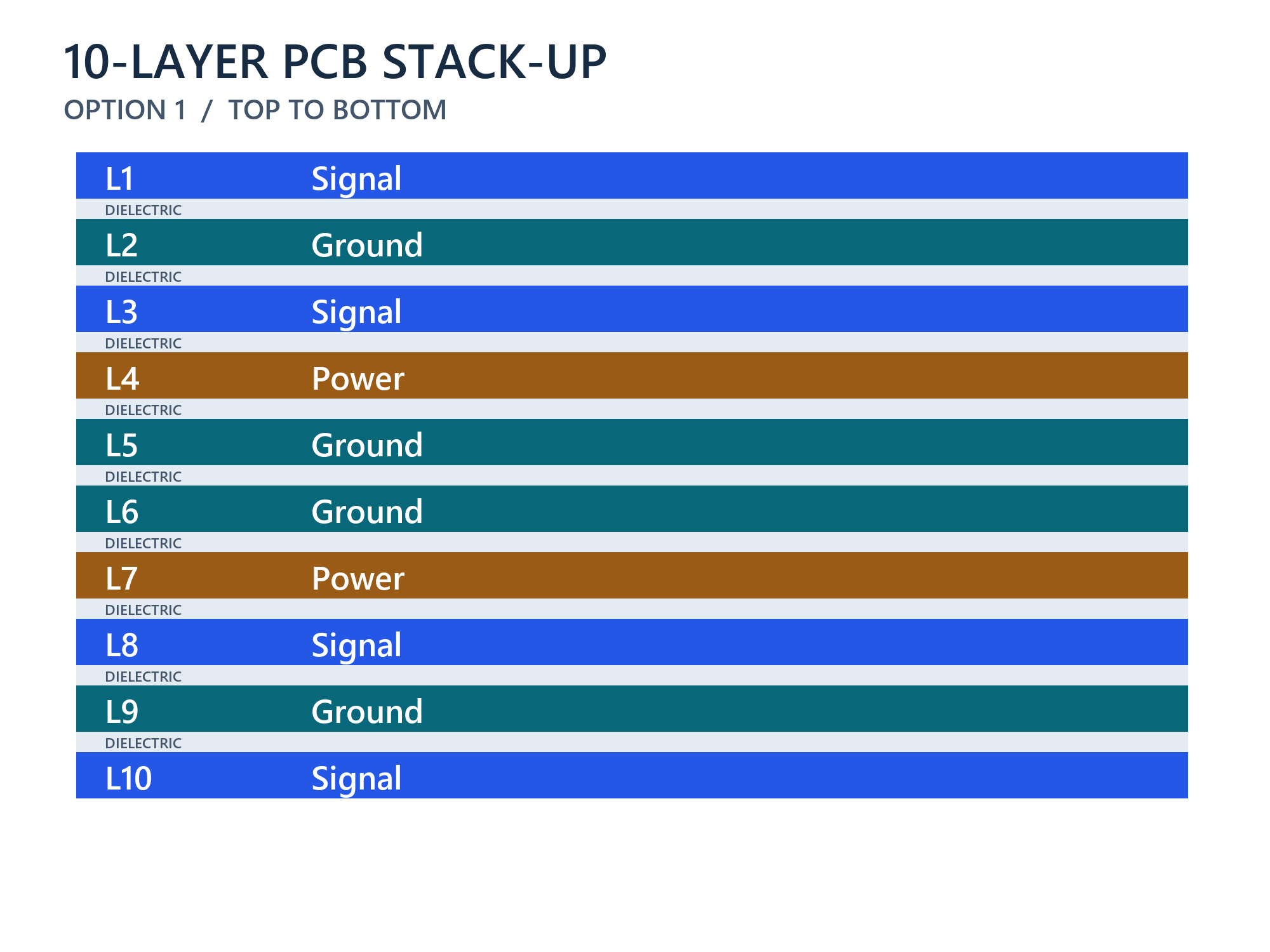
Four Signal Layers, Four Grounds and Two Power Planes
Signal / Ground / Signal / Power / Ground / Ground / Power / Signal / Ground / Signal provides four signal layers, four ground planes and two power layers.
Each outer signal layer has an adjacent ground plane. Review L3 and L8 against their neighboring ground and power planes, including dielectric distances and power-plane partitions.
The L4-L5 and L6-L7 power-ground pairs provide options for power distribution. Specify their spacing and rail areas to meet the current and decoupling requirements.
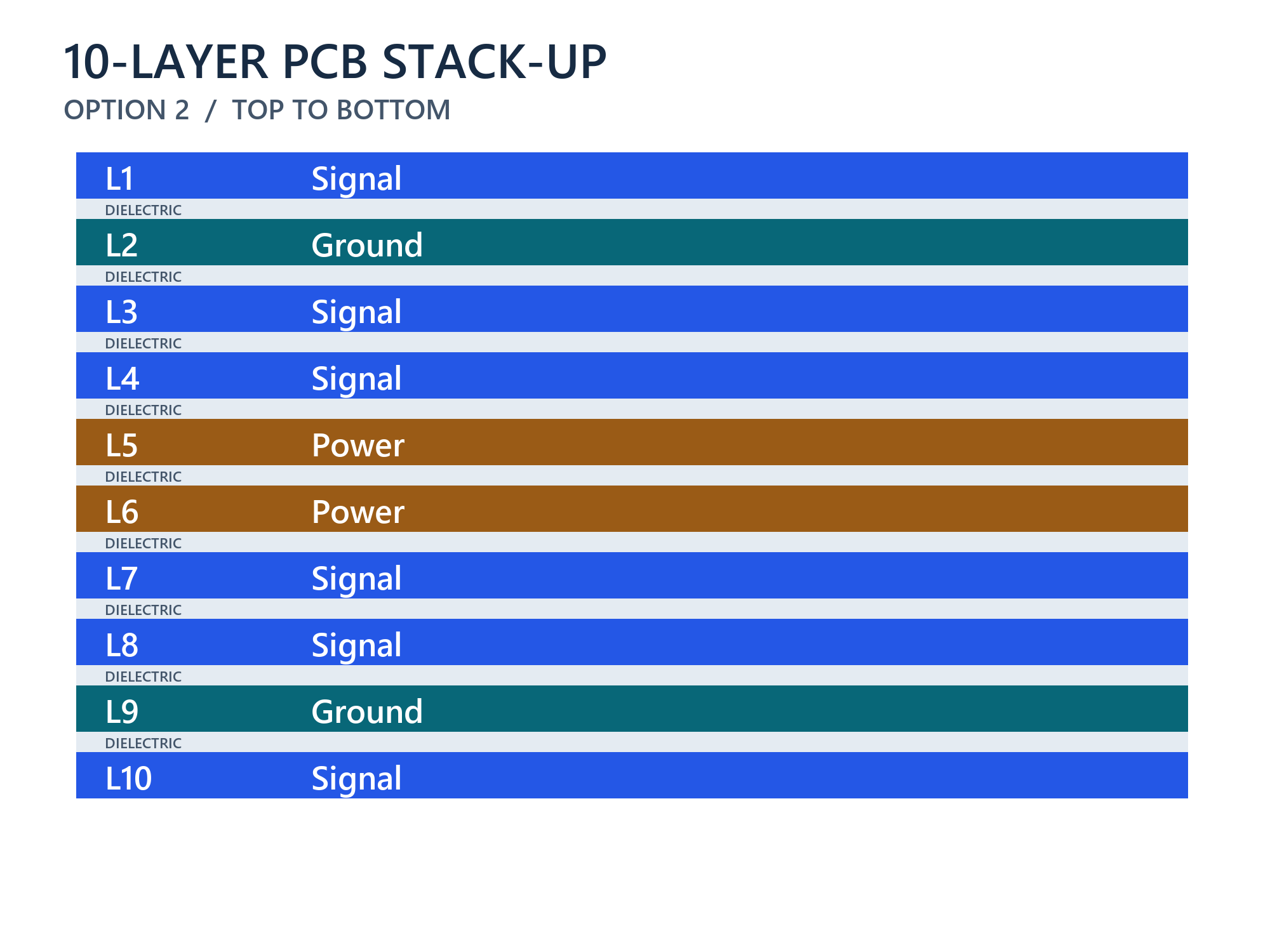
Six Routing Layers with Dedicated Power Planes
Signal / Ground / Signal / Signal / Power / Power / Signal / Signal / Ground / Signal provides six routing layers, two ground planes and two power layers.
Check coupling between adjacent L3-L4 and L7-L8 routes. Their useful capacity depends on reference distances, overlapping routes, interface requirements and clearance around vias.
The central L5 and L6 layers are both power layers. Review return paths for nearby routes and reference transitions with the complete power-distribution network.
Four Signal Layers with Five Ground Planes
Signal / Ground / Signal / Ground / Power / Ground / Ground / Signal / Ground / Signal provides four signal layers, five ground planes and one power layer.
The inner signal layers sit between ground planes. Review their spacing and ground connections, including the return path when signals transition to outer layers.
Plan the power rails within the available plane and routing areas. Additional ground planes provide reference options, while material balance and actual copper distribution still need manufacturing review.

Check the Useful Routing Capacity
A routing layer helps when the design can reach it and maintain the required signal references.
Internal References
Identify the neighboring planes and dielectric distances for each critical signal layer. Check continuity around power partitions, clearances and via fields.
Adjacent Signal Layers
Review overlap, parallel length and separation between routes on neighboring layers. Use interface requirements and analysis where needed; different layer numbers do not establish isolation.
Layer Transitions
Plan return-path connections when signals change layers. Review ground-to-ground transitions separately from transitions involving a power reference.
Plan BGA Escape and Via Access
The added layers must be reachable with a manufacturable interconnect structure.
Package Escape
Provide package part numbers, pitch, land patterns and escape routes. Check that pad and via clearances leave usable channels to the assigned signal layers.
Via Spans and Stubs
Identify the layers used by critical connections and any unused barrel sections. Review their electrical effect before specifying blind vias, microvias or back-drilling.
Manufacturing Sequence
We support conventional multilayer and specified HDI builds. Select drilling, filling and lamination requirements for the approved structure; ten layers alone do not require staged build-up.
Define the Nine Dielectric Regions
Layer functions and physical construction are separate parts of the stack-up specification.
Materials and Pressed Spacing
Identify the material grades and pressed spacing between each pair of copper layers. Review the core and prepreg arrangement with the actual copper patterns.
Copper and Finished Thickness
Distinguish starting foil from finished copper and specify inner and outer requirements. Confirm overall board thickness, tolerance and a complete thickness budget.
Electrical Material Data
Provide dielectric constant (Dk), dissipation factor (Df), data source, frequency and test method. Include copper-roughness and loss requirements where relevant to the interface.
Impedance and Acceptance
Provide impedance targets, tolerances, reference layers, trace widths and pair spacing. Agree on coupons, electrical testing and reports required for acceptance.
Ten-Layer PCB Manufacturing Capabilities
We supply standard and custom constructions from prototypes to repeat production.
Materials and Thickness
FR-4, high-Tg and RF laminate options are available, with standard and custom thicknesses and copper weights selected for the project.
Controlled Impedance
We support single-ended and differential structures, engineering review, impedance coupons and testing as specified.
Interconnect and Surface Finish
Our services include conventional and specified HDI structures, via treatments and surface finish options for the design and assembly.
Inspection and Production
We support prototypes, small batches and production orders, with fabrication inspection and electrical testing. Specify the acceptance criteria and required documentation.
Approve the Build with the Layout
Keep material choices, electrical geometry and production files under one approved revision.
Proposed Construction
Send the layer functions, fixed dimensions and electrical requirements. We review the material and copper arrangement with the manufacturing requirements.
Changes and Substitutions
Review material, dielectric or via-span changes before applying them. Confirm any effect on routing, impedance and mechanical dimensions with the design team.
Production Release
Approve the stack-up, layer file mapping, drill data and tests together. Use the same revision for the drawing and fabrication files.
Files for a Ten-Layer Stack-Up Review
Send the current design package and identify any undecided requirements.
- L1 to L10 functions, layer names and fabrication data
- Board dimensions, finished thickness and tolerance
- Materials, copper requirements and substitution restrictions
- Critical interfaces, impedance targets and trace geometry
- BGA land patterns, drill data and via spans
- Power rails, current requirements and plane allocation
- Quantity, delivery target and required reports
See our PCB fabrication services for the manufacturing scope and our sequential lamination and stacked-via services for staged build-up requirements.
10-Layer PCB Stack-Up FAQs
Ten layers can help if the added layers resolve the identified congestion and the vias can reach them. Mark the blocked routes and reference conflicts, then assign a function to each added layer. Send your current eight-layer stack-up and proposed ten-layer allocation, along with the package escape and interface requirements, for review before rerouting.
Choose based on the routing and reference requirements. Six routing layers add channels but need careful review of adjacent-layer coupling and return paths. A plane-rich build leaves fewer layers for signals. Identify the critical nets and congestion areas. Your design team can then compare routing capacity and signal references while we review the construction for manufacturing.
Yes, if the material and dielectric arrangement can meet both constraints. Send the thickness and tolerance, fixed trace widths and pair spacing, target impedances and reference layers. We review the available materials and dielectric spacing. If the requirements conflict, agree on a change to geometry, material or thickness before releasing production files.
Not from layer count alone. Provide the BGA part number, pitch, land pattern and escape requirements. Check whether through-hole vias leave sufficient channels and reach the required layers. Specify blind, buried or microvia structures where the approved escape and electrical design need them.
Review the unused via-barrel sections on critical routes against the interface requirements. Provide signal layers, via spans, board thickness and any channel analysis. If back-drilling is selected, specify the drilling side, layers that must remain connected, permitted residual stub and depth tolerance on the fabrication drawing. Back-drilling is a project requirement, not an automatic step for every ten-layer board.
Yes, if the proposed build still meets the electrical and mechanical requirements. Send the existing stack-up, material data, impedance table and trace geometry for comparison. Review changes to dielectric spacing, copper, loss characteristics or via construction, then approve updated production files before manufacture.
Discuss Your 10-Layer PCB Stack-Up
Share your ten-layer design, critical interfaces and proposed construction. We will review the stack-up, via plan and manufacturing quotation with your team.