 Skip to content


Inspect Components and Visible Solder Joints
Topline Circuit provides automated optical inspection for PCB assemblies. We check programmed visible features against the approved assembly data, including component presence, position, orientation and accessible solder joints.
Send the current BOM, placement data, assembly drawings and inspection requirements. We review the process stage, board sides and features to be inspected with your assembly order.
Build the Inspection Program Around the Assembly
The inspection reference must match the board revision, component packages and approved assembly variant. Identify polarity marks, alternate parts and do-not-populate positions before the program is released.
Lighting, viewing angles and component geometry affect what can be observed. Tall parts, reflective surfaces and obscured joints are reviewed when defining the optical coverage.
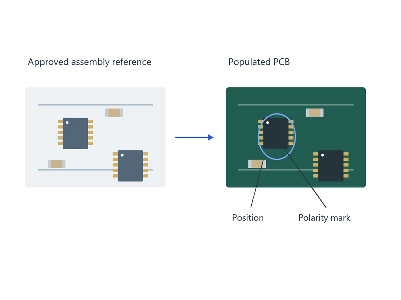
Visible Assembly Features Reviewed by AOI
| Feature | Optical review focus |
|---|---|
| Component presence | Missing or unexpected parts relative to the approved BOM and population rules. |
| Position and rotation | Shifted, skewed or rotated components against the programmed placement criteria. |
| Orientation and polarity | Visible markings and package features that identify the required direction. |
| Lead and component seating | Lifted leads, tombstoning and other seating conditions where the selected view and system support the check. |
| Visible solder features | Accessible bridges and solder-shape differences assessed against the agreed acceptance criteria. |
Define the Inspection Stage and Board Sides

Pre-reflow inspection can check placement before solder joints are formed. Post-reflow inspection evaluates the components and visible joints after soldering.
Identify the required stages and sides in the control plan. For mixed SMT and through-hole assemblies, review optical access after each relevant operation rather than assuming one scan covers every assembly step.
Keep AOI, SPI and Hidden-Joint Inspection Distinct
SPI measures printed solder-paste deposits before component placement. Assembly AOI evaluates components and visible assembly features at the defined stage; it does not directly view joints hidden beneath an opaque package.
Use the appropriate additional methods for hidden joints, electrical values and product operation. Our PCB testing and inspection services explain the wider inspection and test scope.
Review Machine Calls and Verify Corrections
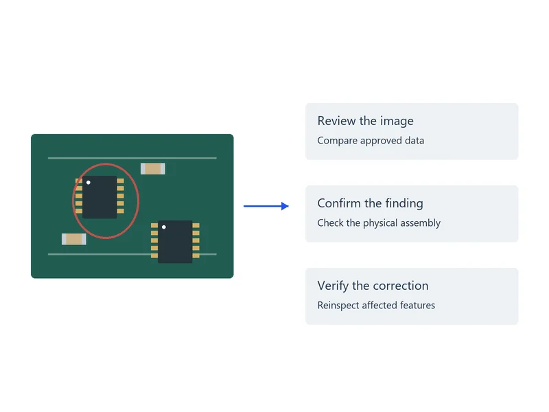
An AOI call identifies a feature that needs evaluation. Review the captured image, approved part information and physical assembly before classifying the condition as a defect.
Hold assemblies with confirmed nonconformances for the agreed action. Where rework is authorized, reinspect affected features and perform the applicable tests before release.
Agree on Coverage, Criteria and Records
- Inspection identity: board revision, variant, program revision, process stage and board side.
- Feature coverage: component groups, visible joints and any obscured locations needing another method.
- Acceptance basis: specified document, revision, class and customer-specific requirements.
- Review outcome: location, image, reported condition and confirmed finding where records are requested.
- Follow-up: authorized rework, reinspection and any additional electrical or functional checks.
Files for a PCBA AOI Review
- Approved BOM with manufacturer part numbers and alternate-part rules
- Pick-and-place data and assembly drawings for both sides
- PCB revision, assembly variant and do-not-populate list
- Polarity instructions and package drawings or marking references where needed
- Required inspection stages, acceptance criteria, quantity and records
AOI is coordinated with our PCB assembly services. Identify any first-article approval or customer review required before repeat production.
PCBA AOI FAQs
Not directly where the package blocks the optical view. Identify the packages and hidden interfaces that need additional inspection, such as an agreed X-ray method. Define electrical and functional tests separately for the connections and operating behavior that must be verified.
Not reliably from appearance alone. Readable markings may support identification, but many parts are unmarked or visually similar. Check the BOM and sourcing records, and specify an appropriate electrical test where the actual value must be verified.
Compare the inspection program with the released assembly variant and do-not-populate list. Confirm that the location is intentionally unpopulated and update the controlled reference if needed. Do not suppress a missing-part check across other variants that require the component.
Provide the updated BOM, placement data, drawings, variant rules and polarity references with clear revision identifiers. Mark the changes and remove obsolete files. Review the inspection program and relevant first-article checks before using the updated version in production.
Review representative images and physical features to distinguish acceptable variation from real defects. Check lighting, alignment, part libraries and revision data before adjusting the program. Verify any revised settings against representative acceptable and defective features rather than simply lowering sensitivity to reduce call counts.
Specify the required images, reference designators, board or lot identifiers, program revision and review outcomes during quotation review. Include rework and reinspection records where needed. We confirm the available record scope and format before production; a machine call log alone does not identify which calls were confirmed defects.
Discuss Your Assembly Inspection Requirements
Send your assembly files and the features that need inspection. We will review the AOI coverage, complementary tests and required records with your assembly order.