 Skip to content


LED Light Boards, Drivers and Controls
Topline Circuit fabricates bare PCBs and assembles boards for LED lighting. Send your light board, driver or dimming controller files so we can review the board construction, component sourcing and test requirements for your quote.
Choose the Board by Its Function
| Board | Typical construction | What to specify |
|---|---|---|
| High-power LED light board | Aluminum metal-core PCB when it meets the thermal and electrical isolation requirements | LED part number and current, dielectric thickness (mm) and thermal conductivity (W/m·K), mounting points and heat sink interface |
| Linear LED strip or light bar | Rigid FR-4, aluminum or flexible PCB, depending on heat load and installation | Finished length and width, connector position, panel layout and edges where breakaway tabs are allowed |
| LED driver or dimming controller | FR-4 with a stack-up suited to the circuit and installation | Input voltage range, output current, load range, dimming interface and applicable insulation requirements |
Specify the Heat Path to the Heat Sink
Send the LED datasheet, operating current, ambient temperature range and mounting drawing. Specify the board material and thickness, copper thickness, dielectric requirements and the thermal interface material between the board and heat sink.
For a thermal check, identify the measurement point specified by the LED manufacturer. Define the mounting setup, drive current, ambient temperature, stabilization criterion and temperature limit. See our aluminum and metal core PCB service for substrate options.
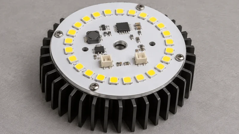
Keep LED Placement and Color Consistent

Specify the LED part number, approved color and flux bins, where applicable, polarity and any placement tolerance needed to align the LEDs with lenses or light guides. If different bins may be used, state whether they may be mixed on one board or within the same production lot.
For long or narrow boards, mark connector access, mounting holes and allowable tab locations. If the fixture depends on the board sitting flat, specify the mounting surface and the flatness requirement on the drawing.
Define Light-Up, Driver and Dimming Tests
For a light-up test, specify the supply or driver settings and which LEDs or channels must illuminate and whether each board must be tested. For a driver board, provide the input voltage (V), representative load, output current limits (mA or A) and the dimming interface and settings to test.
If you need measured light output or color, provide the target values, tolerances and test setup, including whether to measure the bare light engine or the assembled fixture. Include the requested test scope and records in your quote request.
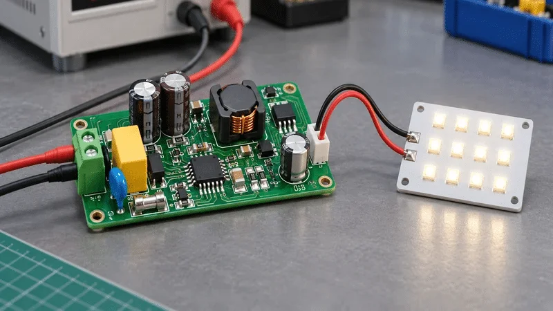
Files for an LED Lighting PCB Quote
- Gerber or ODB++ files, drill data, fabrication drawing and order quantity
- For assembly, add the BOM, pick-and-place data and assembly drawings
- LED part numbers and approved bins, fixture drawings and thermal requirements where applicable
- Test procedure, power and load settings, pass/fail limits and any required reports
See our PCB assembly services for sourcing and assembly options and our PCB testing and inspection services for test planning.
LED Lighting PCB FAQs
FR-4 is an option if the LEDs stay within their temperature limits in the intended fixture. Compare FR-4 and aluminum at the same drive current, ambient temperature and mounting conditions after temperatures stabilize. Measure at the point specified by the LED manufacturer and use its thermal method to estimate junction temperature when the limit is specified at the junction.
Send a dimensioned outline and mark mounting holes, connectors, keep-outs and edges where tabs are allowed. Include the required flatness and panel size limits. Tell us whether you need individual boards or panels for assembly.
List the exact LED part number and approved color and flux bin codes in the BOM. State whether different bins may be mixed on one board or in one lot. If a specified bin is unavailable, tell us whether to hold the build or submit an alternative for approval.
A light-up test checks that the specified LEDs or channels illuminate. For optical acceptance, specify the luminous flux in lumens (lm) or correlated color temperature (CCT) in kelvin (K), with tolerances. Identify whether to measure the light board or finished fixture, and agree on drive current, stabilization conditions, sample size and reporting.
Yes. List the bare light board, assembled light board or driver PCBA you need, with the quantity for each. For each assembly, include its BOM, placement data, assembly drawing and test requirements. If the boards are tested together, include the wiring diagram and define the load and dimming states.
Discuss Your LED Lighting PCB Requirements
Send your board files, order quantity and assembly scope. Include LED bin requirements, mounting details and the tests you need for acceptance.