 Skip to content


Custom Cable Assembly
Specify Your Custom Cable Assembly
Specify the connectors, wiring and finished dimensions for the cable assembly your product needs. A drawing, pinout and estimated quantity give us a starting point to review the build and testing requirements.
Tell us whether the cable connects two devices, links boards inside an enclosure or forms part of a larger assembly. Include mating parts and any installation constraints that affect fit or access.
Confirm Both Connectors and the Pinout
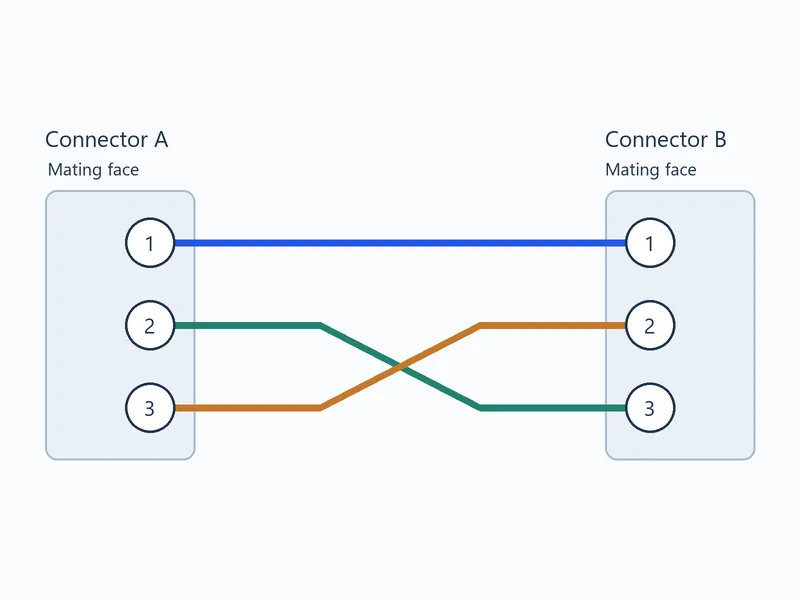
Identify the housing, contacts, seals and accessories at each end by manufacturer and part number. Show the connector keying, latch position and whether the pinout drawing is viewed from the mating face or the wire-entry side.
List each connection by connector ID and cavity number at both ends. Identify unused cavities, jumpers, twisted pairs and any connections to the shield or connector shell.
Cable Assembly Specification Checklist
| Item | What to specify |
|---|---|
| Connectors and contacts | Part numbers, cavity count, keying, contact type and mating parts |
| Wire and jacket | Conductor count, AWG or cross-sectional area in mm², stranding, insulation and jacket requirements |
| Finished dimensions | Overall length in mm, measurement points, tolerances and breakout lengths where applicable |
| Electrical connections | Pin map, pair assignments, shield and drain-wire terminations |
| Mechanical details | Connector orientation, strain relief, bend clearance and labels |
| Acceptance | Inspection and test methods, acceptance limits, test coverage and required records |
Review Termination, Shielding and Installed Fit

Choose a termination compatible with the connector and wire specification. Where crimping applies, confirm that the conductor size and insulation diameter fit the specified contact and tooling requirements.
State where the shield and drain wire connect. Show strain relief, cable exit direction and any space or bend constraints near the connectors. For branched wiring, include the branch lengths, breakout points and fixing locations.
Confirm the Sample Before Repeat Production
Use the approved drawing and bill of materials to check the sample. Confirm pin mapping, length, connector orientation and fit with the mating parts. Record any changes in the drawing revision before repeat orders.
Agree on Inspection and Test Coverage
Define checks for correct wiring, opens and unintended shorts. Agree on the test fixture, limits and reporting requirements before production.
Specify additional tests only as needed for the application. For insulation resistance or dielectric withstand testing, identify the circuits to test and specify the voltage (V), duration (s) and applicable limits, such as minimum insulation resistance or maximum leakage current. For a pull test, specify the sample plan, test method and minimum force (N).

Files for a Cable Assembly Quote
- Dimensioned drawing, pinout and connector part numbers
- Wire specification, shield termination and strain-relief details
- Length tolerances, connector orientation, marking and packaging
- Quantity, delivery requirements and acceptance tests
- Photos, mating parts or a reference sample if drawings are incomplete
If the cable will ship with a board, include the mating connector and installation details in your PCB assembly requirements.
Cable Assembly FAQs
Yes. Send photos of both ends, the approximate length, quantity and intended use. Label the two ends and include mating-part details if known. Use the sample to confirm construction and pin mapping, then approve the drawing and pinout before production.
Review the proposed replacement against the mating part, keying, pin assignments, contact ratings and installation envelope. Check the wire and insulation size against the replacement contact, and confirm fit with the actual mating part. Approve the revised part list and sample before substitution.
Mark the measurement points on the drawing, such as the two connector mating faces, and provide the tolerance. State the measurement condition, such as straight without tension, and whether strain reliefs or backshells are included between the reference points.
Yes. Identical housings can be wired differently. Label both ends, identify the mating-face or wire-entry view, and provide a cavity-to-cavity map. Mark crossed wires, unused positions and shield connections.
No. Verify the intended pin-to-pin paths and check for unintended connections. Add insulation resistance or dielectric withstand testing when the electrical requirements call for it, and pull testing when termination strength must be verified. Agree on the limits and whether each check applies to every unit or to samples.
Add a dimensioned layout with breakout positions, branch lengths, connector orientations, routing and fixing points. Include a from-to wire list and installation constraints for the enclosure.
Send Your Cable Drawing for Review
Share the drawing, connector details, quantity and test requirements. If your design is still in progress, flag the dimensions or parts that need confirmation.