 Skip to content


Load the Approved Firmware for Your Assembly
We provide IC programming for prototype and production PCB assembly, loading approved firmware and configuration into the specified devices. We review the device, programming method, connection and verification requirements before preparing the production job.
Send the full device part number, board revision, program files and instructions. Identify the required programming stage and any unique data so we can define the tooling, approval steps and records for your build.
Choose Programming Before or After Assembly
Off-board programming loads the device before placement using a compatible programmer, socket or adapter. Identify the programmed parts and control their handling so they remain associated with the correct assembly and firmware release.
In-system programming loads the device on the assembled PCB through the supported interface. Review access, board power, reset and boot controls, and any surrounding circuitry that affects communication with the target.

Define the Programming Job
| Requirement | Details to provide | Production control |
|---|---|---|
| Target device | Full manufacturer part number, package and board reference designator | Confirm the device variant and programming support |
| Firmware release | Approved file, format, release identifier and checksum or digest where specified | Link the production job to the approved file revision |
| Memory map | Write addresses, image regions, bootloader and configuration data | Define which regions are erased, written, verified or preserved |
| Connection and power | Interface pinout, supply and reference voltages, reset and boot sequence | Confirm supply and reference voltages in V, current limits in mA or A, and fixture connections |
| Device configuration | Option bytes, fuse settings and required protection state | Approve the device-specific order of operations |
| Unique data | Serial numbers, MAC addresses or other per-unit data and their allocation rules | Control assignment, verification and failed-attempt handling |
| Verification | Supported readback, checksum or tool verification, plus specified startup checks | Record the method and acceptance result for each required operation |
| Traceability | Unit or batch identifier, hardware revision and reporting requirements | Link results to the delivered configuration |
Match the Interface to the Actual Device
Programming routes can include SWD, JTAG, device-specific ISP or a supported bootloader over an interface such as UART. The available route depends on the exact device and board design, not only the connector label.
Provide numbered connections for ground, target voltage reference, programming signals and reset or boot controls. Identify whether the board or programmer supplies power, and define the required voltage, current limits and power-up sequence.
Release the Image, Addresses and Configuration Together

Keep the approved firmware image, file format, target addresses and configuration settings in one controlled programming package. Specify the required programmer job and tool version where the process depends on them.
Define the erase scope and any memory regions that must remain unchanged, including calibration, identity or customer data. For rework or updates, approve a separate procedure that preserves the required data and handles the existing protection state.
Control Unique Data and Protection Settings
For serialized products, define the data source, allocation range, memory location and duplicate-checking rules. Record what happens to an allocated identifier when programming fails or a board is retested.
Approve protection settings and the point at which they are applied, including how the required verification will be completed. If keys or credentials are involved, define their secure transfer, access and provisioning procedure separately from the general enquiry.
Verify the Programmed Device and Board Startup
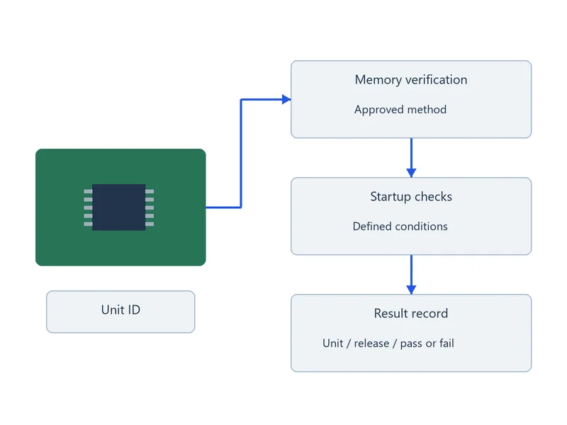
Define how written memory and device settings will be verified, using the supported tool and approved procedure. A matching firmware file digest identifies the input file; it does not prove that the device memory, addresses or configuration are correct.
Specify startup checks and any separate functional tests, with their connections, operating conditions and pass/fail limits. Link the programming result to the unit identity and firmware release, and retain failure and retest records.
Files for an IC Programming Quote
- Full device part number, package, reference designator and hardware revision
- Approved firmware files, format, release identifier and address map
- Bootloader, option-byte, fuse and protection requirements where applicable
- Interface pinout, power requirements and programming sequence
- Existing programmer project, tool version, socket or fixture details where available
- Erase and preserve instructions for calibration or other retained memory
- Unique-data requirements, verification criteria and requested records
- Build quantity, programming stage and first-article approval requirements
Programming can be included in your PCB assembly order. If the release is preliminary, identify the open items so we can distinguish the quotation scope from the approved production job.
IC Programming FAQs
A file can support an initial review, but production also needs the exact target device, hardware revision, programming addresses and configuration. A BIN file requires its load address to be defined; a HEX file still needs a confirmed device and memory map. Provide the connection, power and verification instructions, then approve the complete programming job before production.
Choose the stage according to device support, package handling, board access and the release plan. Off-board programming needs a compatible socket or adapter and identification of the programmed stock. Board-level programming needs accessible signals, controlled power and a repeatable connection. Confirm the route before parts are prepared or fixtures are made.
Keep the programming result and identify the affected unit, image and job revision.
Check the device variant, addresses, boot and reset configuration, supply and required clock conditions against the approved procedure. Confirm that any bootloader and application images are compatible. Programming verification and board startup are different checks; record the fault and repeat the required tests after correction.
Define the approved identifier source, format, address and assignment rules for the supported device. Provide a duplicate-checking method and a record linking each identifier to its unit. Define whether a failed attempt keeps the identifier reserved for the same unit or retires it.
Prevent an identifier from being assigned to two units, and verify the written data before releasing the board.
That depends on the device and the erase operation used. Identify the memory regions that must be preserved and provide the approved update procedure before reprogramming. Review existing protection settings and any required backup or recovery steps.
If the data cannot be preserved using the proposed operation, stop and obtain an approved recovery or replacement plan before erasing. Verify retained data and the new firmware after the update instead of assuming that a full-chip erase is acceptable.
Release the approved image and programming job with the hardware revision and effective batch or serial-number range. Archive superseded jobs outside normal production access and verify the selected release on the first article. Keep the required programming result linked to each unit or batch.
If the firmware changes during production, identify affected work in progress and approve its disposition before continuing.
Prepare Your Programming Release
Send the device details, firmware revision and programming requirements. We will review the connection, tooling and verification scope for your assembly.