 Skip to content


Integrate Your PCBA into a Complete Product Assembly
We provide box build assembly that combines PCBAs, wiring and mechanical parts into the agreed product configuration. Services can include enclosure assembly, cable integration, firmware loading, system testing, labeling and packaging.
Tell us whether you need an open subassembly, a closed enclosure or a configured packaged unit. Send the electrical and mechanical files so we can define the material responsibilities, assembly steps and acceptance requirements.
Define the Finished Unit and Who Supplies Each Item
Box build goes beyond populating a circuit board. The scope can include installing PCBAs, power supplies, displays, fans, switches and sensors, then connecting and securing the internal wiring.
Identify who supplies each board, enclosure, cable and mechanical item. We can coordinate PCB fabrication and component procurement or integrate agreed customer-supplied parts, with the responsibilities recorded in the system BOM.
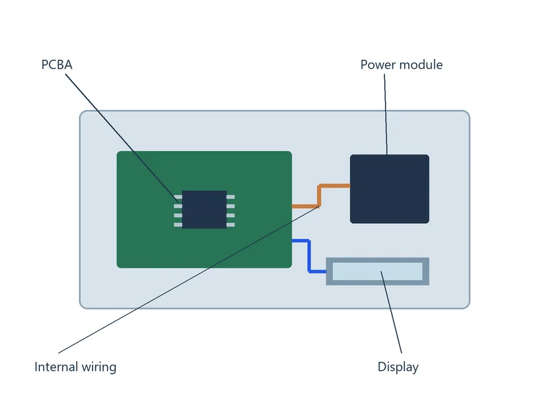
Box Build Integration Scope
| Service | Assembly scope | Required definition |
|---|---|---|
| PCBA integration | Mount boards and associated modules | Board revision, mounting hardware, orientation, clearances and access. |
| Enclosures and mechanics | Install covers, brackets, controls and mechanical parts | Released drawings, dimensions and tolerances, fasteners, torque requirements and assembly sequence. |
| Cables and harnesses | Connect, route, retain and identify wiring | Pinout, connector/contact part numbers, wire gauge (AWG or mm²), length tolerance and strain relief. |
| Thermal interfaces | Fit specified heat sinks, fans and interface materials | Contact areas, material thickness, orientation and mounting instructions. |
| Firmware and configuration | Load approved software and configure the unit | Image revision, device, settings, verification and identity requirements. |
| System testing | Perform agreed checks on the integrated unit | Connections, fixtures, supply voltage/current limits, loads, test duration, pass/fail criteria and records. |
| Labels and packaging | Apply unit identification and prepare the shipment | Approved artwork, serial-number rules, accessories and packaging specification. |
Resolve Mechanical Fit Before Releasing the Build
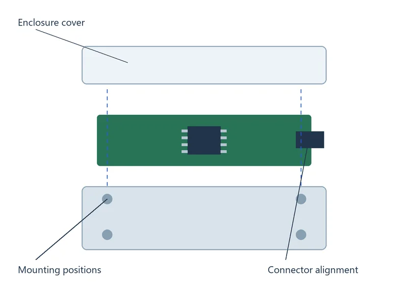
Provide dimensioned mechanical drawings, 3D CAD and an exploded assembly view where available. Review board mounting, connector alignment, component clearances and access for assembly and service.
Specify fastener type, torque value and tolerance with units such as N·m, tightening sequence and any locking or bonding materials. Use an agreed first-article review to check fit and assembly sequence before releasing the remaining units.
Control Harness Connections and Internal Routing
Define connector part numbers, contact assignments, wire sizes, lengths and any shield or grounding requirements. Mark connector orientation and pin numbering clearly, supported by a wiring diagram.
Show routing, retaining points, bend restrictions and strain relief. Review clearances from sharp edges, moving parts and heat sources, then define the continuity, pinout and other electrical checks required before closing the enclosure.
Test the Integrated Unit, Not Only the Board
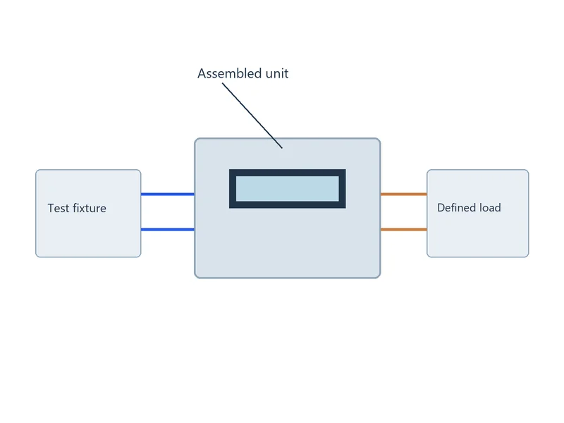
A PCBA can pass board-level checks while the finished unit still has wiring, configuration, cooling or mechanical faults. Define system tests for the actual assembled configuration, with the required loads, connections and operating conditions.
Provide supply limits, fixture instructions and pass/fail criteria for each test. Where specified, define protective-earth continuity or dielectric withstand checks with the tested connections, method, limits and duration.
Link Firmware, Unit Identity and Shipment Contents
Identify the approved firmware image, configuration, product variant and serialization rules. Record verification results against the unit identity so labels and test records refer to the delivered configuration.
Define accessories, cables, instructions and packaging by variant. Our turnkey PCB assembly service covers the related board and component supply responsibilities when these are included in the box build.
Files for a Box Build Assembly Quote
- System BOM with part numbers, revisions and supply responsibilities
- PCBA fabrication and assembly files, or supplied-board specifications
- Mechanical drawings, 3D CAD, exploded views and critical tolerances
- Harness drawings, pinouts, wire specifications and connector details
- Fastener, torque, adhesive and thermal-interface instructions
- Firmware, configuration, serial-number and label requirements
- System-test procedures, fixtures, operating limits and acceptance criteria
- Quantity, first-article hold points, shipment contents and packaging
Preliminary files can support an initial review. Our PCB assembly team can identify open items before the system configuration and production instructions are approved.
Box Build Assembly FAQs
Turnkey PCB assembly coordinates boards, components and board population. Box build adds the specified mechanical parts, wiring and product configuration around the PCBA. State whether the deliverable is a subassembly or a complete enclosed unit, and define system testing and packaging separately.
Yes. Identify each supplied item by part number, revision, quantity and condition. Agree on receiving checks, handling and shortage actions, and provide the drawings needed to confirm compatibility. Separate customer-supplied items from materials we need to procure in the system BOM.
Hold the affected assembly and record the unit, part revisions and measured interference. Do not force the connector or modify the board or enclosure without approval. Compare the actual dimensions with the released mechanical and PCB drawings. Review any board, bracket or enclosure change with the responsible design team, then approve the correction and verify fit before continuing the build.
Define whether you will supply finished harnesses or require their manufacture within the order. Provide connector and contact part numbers, pinouts, wire size, length and shield requirements. Agree on routing, strain relief and the required continuity and pinout checks before assembly.
Follow the approved power-down and fault-isolation procedure before opening or adjusting the unit. Check wiring and connector orientation, supply settings, firmware configuration, mounting clearances and the cooling interface. Verify the fixture and test connections before tracing the fault to the board or another assembly. After correction, repeat the affected checks and required system tests against the approved procedure.
Provide a controlled variant list linking the system BOM, firmware revision, settings, label artwork and shipment contents. Define serial-number allocation and the verification steps for each variant. Keep the unit identity linked to the loaded configuration and final test record before packaging.
Discuss Your Box Build Project
Send your system BOM, mechanical drawings and test requirements. We will review the material supply, integration steps and acceptance scope for your finished assembly.