 Skip to content


Scored Panels for Assembly and Separation
Topline Circuit provides V-scoring for rigid PCB panels from prototypes to production. We review the score layout, remaining web thickness and assembly requirements to support panel handling and separation into individual boards.
Send your panel drawing, board construction and depaneling requirements. We check the score lines, copper clearances and component access before confirming the manufacturing plan.
V-Grooves Leave a Supporting Web
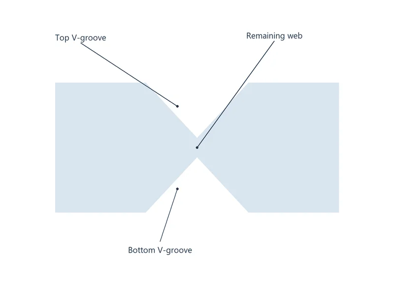
V-scoring, also called V-cutting or V-grooving, forms grooves along the planned separation lines. In a typical double-sided construction, aligned grooves are cut into the top and bottom surfaces while a web of material remains between them.
The web holds the PCB units together through handling and assembly. Its thickness must suit the panel stiffness, material and intended separation method.
Choose V-Scoring or Tab Routing
| Method | Panel structure | What to review |
|---|---|---|
| V-scoring | Straight separation lines leave a residual web between adjacent units. | Score-line continuity, remaining web, copper clearance and depaneling-tool access. |
| Tab routing | Routed channels follow the profile, with selected tabs retaining the boards. | Irregular outlines, tab locations, component clearance and edge remnants. |
| Combined scoring and routing | Scored straight sections are used with routed features where the panel layout allows. | Panel support, tool run-out, sequencing and the final separation method. |
Define the Remaining Web, Not Just the Groove Depth
Specify the required remaining web thickness and its tolerance with the finished board thickness. For aligned top and bottom grooves at the same cross-section, the web equals the board thickness minus the two groove depths.
A fixed fraction of board thickness is not a complete manufacturing requirement. We review the web, material, panel span and assembly loading together before agreeing on the scoring construction.
V-Scoring Requirements for Manufacturing
| Requirement | What to define |
|---|---|
| Panel and unit dimensions | Finished panel size, PCB arrangement, rails and the required dimensions after separation. |
| Score-line locations | Centerlines located from drawing datums, including which lines continue through the panel. |
| Groove geometry | Full included angle between the two groove faces, with top and bottom groove depths defined from their respective board surfaces. |
| Remaining web | Residual material thickness and tolerance between aligned opposing groove roots, measured through the board thickness. |
| Groove registration | Permitted offset between the upper and lower score lines, separately from their position on the panel. |
| Edge acceptance | Dimensions, burrs, exposed fibres and other specified edge criteria after depaneling. |
Protect Copper and Allow Depaneling Access
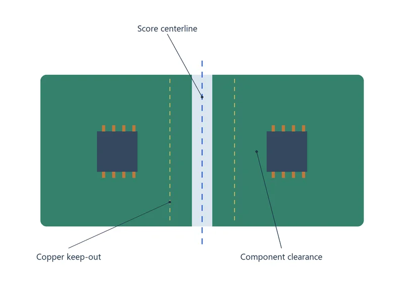
Review copper clearance on every layer against the V-groove geometry and scoring position tolerance. State whether a dimension is measured from the score centerline, groove edge or final separated board edge.
Check component bodies, leads, overhangs and fixtures against the depaneling tool and board support. Keep sensitive components away from high-strain separation areas and agree on the separation method before assembly.
Straight Lines, Rails and Mixed Panel Features
Conventional continuous scoring follows straight lines across the panel. Mark any interrupted or jump-scoring request with its start and stop positions so the layout and manufacturing route can be reviewed.
For irregular profiles, review a combined routed and scored panel. Identify assembly rails, tooling holes, fiducials and any features that must remain supported until the final separation step.
Files for a V-Scoring Quote
- Gerber or ODB++ data, drill files and a fabrication drawing
- Panel drawing with score centerlines, unit arrangement and rail dimensions
- Material, finished board thickness and relevant tolerances
- Required residual web, groove angle and scoring registration criteria
- All-layer copper clearances and component or fixture keep-outs
- Depaneling method, quantity and required inspection records
Our PCB DFM review checks the score plan with the board data. See our PCB fabrication services for the wider manufacturing scope.
PCB V-Scoring FAQs
Use V-scoring where straight separation lines, suitable copper clearance and tool access fit the panel. Choose tab routing for profiles that need routed contours or selected attachment points. Review a combined layout if only part of the board edge suits scoring.
Check the measured residual web, board thickness, material and panel span against the approved requirements. Review rail support, handling and assembly loading. Set aside panels with premature cracks and provide measurements and photos. Review whether a revised web, added support or a different panel layout is needed before continuing assembly.
State the residual thickness between the top and bottom groove roots, its tolerance and the finished board thickness. Include the groove angle and any required registration criteria. Avoid relying only on a one-third-thickness note or two nominal groove depths without a residual-web requirement.
Define the measurement reference first. Copper clearance must account for the groove opening, layer position and scoring tolerance; component clearance must also allow blade travel and board support during separation. Provide the component outline and selected depaneling method so the keep-outs can be reviewed.
An irregular board may suit a combination of scoring and routing. For interrupted lines, identify the required start and stop locations and retained panel support for review. Do not assume a normal continuous-scoring callout requests jump scoring.
Set aside affected boards and record the defect locations, photos and separation method. Compare the web thickness and edge condition with the approved drawing, then inspect nearby copper, vias and components as appropriate. Review tooling, support and panel design before deciding on acceptance, qualified repair or replacement.
Review Your V-Scoring Panel
Send your panel files and assembly requirements. We will review the score geometry, panel support and separation plan and prepare a manufacturing quotation.