 Skip to content


Rigid-Flex PCB Stack-Up
Align rigid and flexible regions, shared copper layers and the installed shape.
Connect the Regions with One Defined Construction
We manufacture rigid-flex PCBs for prototypes and production, with engineering support for regional stack-ups, material selection, controlled impedance and via construction. We review how the rigid sections support components and how the flexible layers connect them in the installed assembly.
A rigid-flex PCB stack-up needs more than a total layer count. Define which copper layers continue through each flex region, where rigid materials end, and the finished thickness of every region.
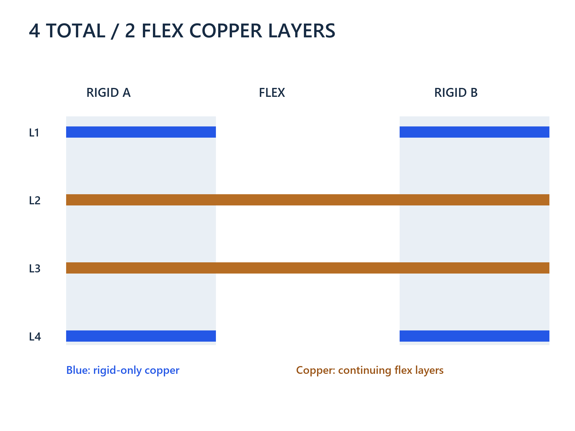
Four Total Layers with Two Flex Layers
In this example, L2 and L3 continue through the flex bridge. L1 and L4 exist in the rigid sections only. The rigid region therefore contains four copper layers and the flex region contains two.
This allocation provides two additional copper layers in the rigid regions for routing or reference functions. Assign their electrical roles and review the via connections to the shared flex layers.
The two flex layers are already included in the four-layer total. The diagram shows copper continuity; the actual laminate, bonding and protection layers are specified separately.

Six Total Layers with Two Flex Layers
L3 and L4 continue through the flexible span, while L1, L2, L5 and L6 remain in the rigid regions. This provides six copper layers in each illustrated rigid region and two in the flex.
Additional rigid-region routing does not add routing layers to the bridge. Plan how signals reach L3 and L4 before crossing the boundary, and maintain the required return paths.
Define the material and finished thickness for each region. The rigid-region board thickness is not the thickness used to assess the flexible span.
Eight Total Layers with Four Flex Layers
L3 through L6 continue into the four-layer flex region. L1, L2, L7 and L8 are confined to the rigid sections. The full illustrated rigid section has eight copper layers.
Four flex layers provide more routing and reference options than a two-layer bridge. Review those benefits with the bonded thickness, copper arrangement and intended bending duty.
If separate flex leaves or unbonded regions are required, document their individual constructions and free lengths. They need a different mechanical and fabrication review from a fully bonded span.

Map Every Copper Layer by Region
Use the same copper IDs in the layout, stack-up drawing and manufacturing files.
Total and Flex Counts
State the copper count for each rigid region and each flexible span. Shared flex layers are included in the rigid-region total; do not add them a second time.
Continuing Layers
Identify exactly which layers cross each boundary. A six-layer region with two flex layers does not define whether those are L2-L3, L3-L4 or another approved arrangement.
Different Regional Builds
Name each region and assign its construction. Multiple rigid islands or flex branches can require distinct thicknesses and layer mappings.
Specify Materials Where They Are Used
Show material identity, thickness and regional extent in the fabrication drawing.
Rigid Laminates and Bonding
Select rigid cores and the appropriate bonding or prepreg system for the construction. Define resin control and the edge of the rigid build around the flexible opening.
Flexible Laminate
Specify base-film grade, copper type and adhesive or adhesiveless construction. Distinguish starting foil from finished copper after processing.
Coverlay and Adhesive
Define coverlay film, adhesive, openings and termination locations. Any overlap into the rigid section is a construction-specific detail to review, not a universal requirement.
Regional Thickness
Specify finished rigid and flex thicknesses separately, with tolerances and measurement locations. Include local protection, finish and support materials where present.
Engineer the Rigid-to-Flex Transition
The boundary brings material, geometry and electrical requirements together.
Mechanical Boundary
Identify rigid edges, bend axes and the installed bend envelope. Review the transition between supported and flexible material before fixing the fold location.
Copper and Plated Features
Define setbacks for vias, pads and components from the boundary and bending span with the approved construction. Review copper changes and trace geometry near the transition.
Protection and Resin Control
Coordinate coverlay edges, adhesive flow and rigid-region bonding. Include strain relief or other local features when required by the selected build.
Choose Vias for the Required Layer Connections
Total layer count alone does not determine whether a rigid-flex design needs HDI.
Through-Hole Structures
Map connections through the complete local rigid stack. Review drill spans, clearances and access to the continuing flex layers.
Blind, Buried and Microvias
Select the via spans needed for escape routing and electrical requirements. Match the drilling, filling and lamination sequence to the chosen construction.
Features in the Flex
Identify any plated features in flexible regions separately. Review their position against motion and transition requirements rather than applying rigid-region rules to the span.
Maintain Signal References Across the Boundary
Continuous copper does not automatically produce the same impedance in both regions.
Regional Electrical Geometry
Provide signal and reference layers, copper, dielectric spacing and relevant material properties for each region. Include coverlay and adhesive effects where applicable.
Reference Changes
Identify where reference copper ends or changes. Plan return-current paths and transitions with the interface requirements, routing geometry and any available channel analysis.
Acceptance and Reports
Specify impedance targets and tolerances. Agree on the coupon structures, electrical tests and reports needed to represent the required regional constructions.
Check the Folded Assembly Before Release
Use the actual flexible-region construction and the complete installed geometry.
Installation or Repeated Motion
Provide bend angle, direction, minimum radius, assembly handling and operating environment. For moving interconnects, add the motion path, cycles and validation requirements.
Space and Component Clearance
Include rigid-region outlines, component heights, mounting points and tolerances. Check the folding sequence as well as the final installed position.
Bonded or Separate Leaves
Specify which layers remain bonded and which spans are intentionally separate. Review relative lengths, fold geometry and local strain for the chosen arrangement.
Rigid-Flex Manufacturing Support
Our services cover stack-up engineering, fabrication and assembly support.
Construction and Materials
Integrated rigid-flex builds with internal or external flex arrangements, regional material selection and custom thickness requirements.
Interconnect and Electrical
Conventional and HDI structures, controlled impedance, via treatments and surface finishes selected for the design.
Prototype to Production
Prototype and production orders with fabrication inspection, electrical testing and assembly support. Agree on the acceptance criteria and documentation for the project.
Files for a Rigid-Flex Stack-Up Review
Send the available design package and identify which requirements are fixed.
- Layer map with copper IDs and named rigid and flex regions
- Gerber or ODB++ data, drill files and fabrication drawing
- Material proposal, copper requirements and regional thickness tolerances
- Flat outline and installed drawing or 3D model
- Bend axes, angles, radii, motion duty and assembly sequence
- Via spans, critical interfaces and impedance requirements
- Quantity, delivery target and inspection or reporting needs
- For assembly projects: BOM, placement data and assembly drawing
Our PCB fabrication services cover the wider manufacturing scope. See sequential lamination and stacked vias when your selected interconnect structure requires staged build-up.
Rigid-Flex PCB Stack-Up FAQs
No. In a six-total-layer construction, the continuing flex layers are already included in that total. For example, L3 and L4 can form the two-layer flex span while L1, L2, L5 and L6 remain in the rigid regions. Put the copper IDs beside each region so the layer count is unambiguous.
It may be possible if the flexible-region materials and copper remain unchanged. Identify the added rigid layers and their connections, then review the bonding sequence, plating effects and transitions. Confirm the finished flex thickness in the revised stack-up instead of assuming it stays unchanged.
Set the clearances for the selected construction and bend envelope. Send the region boundary, nearby pads and vias, component layout and installed bend geometry. We review the manufacturing setbacks with your design team before the drawing is released. If the available space is insufficient, revise the feature locations, transition geometry or selected construction before routing is finalized.
Yes, with the electrical geometry and return path reviewed in both regions. The dielectric, protection and reference arrangement can change at the boundary. Provide impedance targets, trace dimensions and reference layers, then review any geometry changes and acceptance tests before layout release.
No. Through-hole constructions can meet the requirements of many rigid-flex designs. Use the package escape, routing density, layer access and electrical requirements to decide whether blind vias, buried vias or microvias are needed. If they are selected, review a construction and lamination sequence for those spans rather than reusing a through-hole stack unchanged.
Compare the installed model with the actual regional thicknesses, bend axes, radii, rigid outlines, mounting tolerances and component heights. Check the assembly sequence and any separate flex leaves. Send the flat drawing and installed model so the geometry and construction can be reviewed together before production.
Discuss Your Rigid-Flex PCB Stack-Up
Share your regional layer map, design files and installed geometry. We will review the rigid-flex construction and manufacturing quotation with your team.