 Skip to content


PCB DFA Check
Check Your Design Before PCB Assembly
Our design for assembly (DFA) review checks whether your PCB layout, component choices and assembly files suit the planned production process. We compare the BOM, placement data and board artwork to identify conflicts before assembly.
Send your project files and any known concerns. Our engineers explain the issues found and discuss corrections with your team before revised design data is released for production.
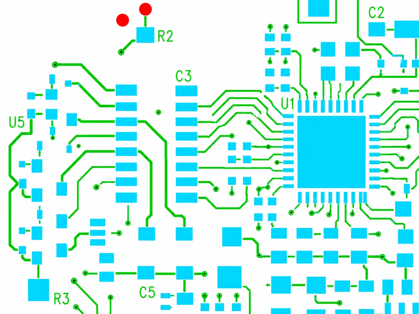
What Our DFA Review Covers
We check the assembly data against the component packages and planned process. The review covers single- and double-sided SMT, through-hole and mixed-technology assemblies.
BOM and Placement Data
Compare reference designators, quantities, manufacturer part numbers and assembly sides. Identify duplicate entries and missing placements, and confirm which parts are marked do not populate (DNP).
Footprints and Land Patterns
Compare the specified component package with the PCB footprint, pin arrangement and available land-pattern data. Request package drawings where the part number or footprint is unclear.
Polarity and Orientation
Check pin 1, diode and polarized capacitor markings, connector orientation and placement rotation against assembly drawings and component datasheets.
Component Spacing and Access
Review component clearances, heights and board-edge distances for placement, soldering, inspection and rework. Assess spacing against the actual package and planned process.
Soldering and Stencil Openings
Review paste-layer apertures, exposed thermal pads, nearby vias and solder-mask features for the selected packages. Identify features that need clarification before stencil preparation.
Panel Handling and Test Access
Review fiducials, tooling features, support areas and clearance for panel separation. Check access to specified test points and programming connectors when test information is supplied.
DFA Capabilities and Package Coverage
Small and Fine-Pitch Packages
DFA review for 01005, 0201 and 0402 chip components (imperial package codes), QFP, QFN, LGA, BGA and micro-BGA packages. Check package dimensions, pin pitch, land patterns and placement clearances.
BGA and Exposed-Pad Features
Review ball-to-pad alignment, solder-mask-defined and non-solder-mask-defined pads, via-in-pad features and thermal-pad paste segmentation. Define X-ray inspection requirements for hidden solder joints during assembly planning.
Soldering Process Compatibility
Review reflow, selective and wave-soldering requirements for the component mix. Check temperature limits, component shadowing, pad thermal balance and features associated with tombstoning or solder bridging.
Board Types and Support
Support DFA review for rigid, multilayer, HDI, flex and rigid-flex boards. Review assembly carriers, support areas, stiffeners and protection of flexible sections during handling.

Review the Details That Affect Assembly
For SMT PCB assembly, we review package spacing, placement orientation and soldering details together. Small components beside tall parts, exposed pads and crowded board edges need attention during process planning.
For BGA PCB assembly, include the package datasheet and relevant land-pattern notes. We review pad and paste features, via placement and inspection requirements for hidden solder joints.
Tell us which components are temperature-sensitive, supplied by your team or excluded from assembly.
Feedback Your Team Can Act On
When we identify an issue, we explain what needs attention and the information needed to resolve it.
Locate the Issue
We identify the affected component reference, footprint or location so your team can locate the issue in the design.
Explain the Impact
We explain how the issue affects assembly and identify the requirement that needs clarification.
Agree on a Resolution
We discuss a practical correction or request missing information. Your team approves design changes before we use the revised files for production.
Files for a DFA Check
Send the files for the same design revision and identify any undecided details. Tell us whether you need assembly only or PCB fabrication and assembly.
- Gerber or ODB++ board data, including solder-mask and paste layers
- BOM with manufacturer part numbers, reference designators and quantities
- Pick-and-place file with coordinates, rotation, units and assembly side
- Assembly drawings showing polarity, special instructions and DNP parts
- Datasheets for custom, unusual or ambiguous component packages
- Panel drawings, test instructions and programming requirements, if applicable
See our PCB assembly services for sourcing, assembly and inspection options.
DFA Check FAQs
No. Gerber files show board features but do not fully identify the parts or their intended placement. Send the BOM, pick-and-place file and assembly drawing with the board data so we can compare the components, footprints and orientation instructions.
Send your BOM, board data and assembly drawing, and tell us which CAD software you use. We can identify which checks those files support and explain what placement information is missing. If the placement file is unavailable, we will discuss the data needed to define and confirm component positions, rotation and assembly side.
Yes. We compare the specified part packages with the available footprint and land-pattern information. Include the complete manufacturer part number and datasheet for unusual or ambiguous parts. If a package drawing or footprint dimension is missing, we will ask for it before confirming the match.
Mark pin 1, diode polarity, polarized capacitors and connector orientation clearly in the assembly drawing. Keep these instructions consistent with the silkscreen and placement file. Include datasheets when package markings are ambiguous so we can resolve conflicts with you.
We identify the affected component or location, explain the assembly concern and suggest a correction or request clarification. Your team approves design changes before revised files are used for production. Label each updated file with its revision and state which earlier files it replaces.
No. DFA reviews assembly suitability before production. Functional testing checks how the assembled board operates and needs a separate test procedure. Send the functions to check, pass/fail criteria, firmware and any fixture requirements so we can review the test scope with you.
Ready to Review Your PCB Assembly?
Send your BOM, board files and placement data. Our team will review the assembly requirements and discuss any details that need your confirmation.