
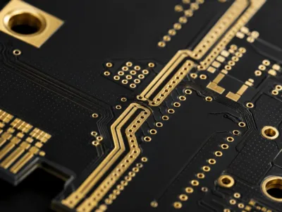
Rogers materials are commonly selected for high-frequency circuits where signal integrity is more important than Rogers PCB vs FR4 PCB
Rogers materials are usually selected when the project needs better RF performance than standard FR4 can provide. The main concern is not only material cost. Buyers also need to check signal loss, impedance stability, dielectric behavior, and stack-up requirements before production.
| Comparison Item | Rogers PCB | FR4 PCB |
|---|---|---|
| Dielectric loss | Lower loss for high-frequency signals | Higher loss at higher frequencies |
| Dielectric stability | More stable for RF designs | Suitable for general electronics |
| Impedance control | Better for sensitive RF paths | Depends more on stack-up tolerance |
| RF and microwave use | Commonly selected | Limited for demanding RF circuits |
| Cost consideration | Higher material cost | Lower material cost |
FR4 is still suitable for many standard electronic products. Rogers material is more suitable when RF signal quality, antenna performance, or microwave circuit behavior needs closer control.
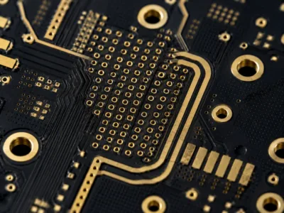
Supported Rogers Materials
Different Rogers materials are used for different frequency ranges and circuit requirements. The final material should be confirmed from the project design, stack-up notes, impedance requirements, and application environment.
| Material | Common Project Use | Buyer Check |
| RO4350B | RF modules and antenna circuits | Confirm stack-up and impedance needs |
| RO4003C | High-frequency communication boards | Check dielectric and copper requirements |
| RO3003 | Radar and microwave circuits | Review frequency and loss requirements |
| RO3010 | Power amplifier and radar designs | Confirm thermal and RF design needs |
| RT5880 | Satellite and microwave applications | Check material availability and design limits |
| RT6002 | RF and microwave circuits | Review project-specific material requirements |
Rogers and FR4 hybrid stack-ups can also be considered when only part of the circuit needs RF material. This should be reviewed before quotation because hybrid stack-ups affect material planning, lamination, and manufacturing control.
Engineering Review Before Production
Rogers PCB projects need careful review before production release. Material choice, dielectric spacing, copper thickness, trace geometry, ground reference, and via transition can all affect signal behavior.
Stack-up review should confirm the relationship between signal layers, reference planes, dielectric thickness, and impedance targets. If these details are unclear, the board may pass basic fabrication checks but still create RF performance problems later.
Impedance control should be marked clearly in the design files. Buyers should show which traces require controlled impedance and what values need to be checked during engineering review.
RF routing areas should also be reviewed before fabrication. Transmission lines, antenna feed paths, RF connectors, and grounding structures may need special attention during manufacturing review.
Manufacturing Support
This page does not use fixed capability numbers because Rogers PCB requirements depend on material type, stack-up structure, copper design, impedance targets, and customer files. Project details should be checked before quotation and production release.
| Support Area | What We Review |
| Material selection | Rogers grade and FR4 hybrid needs |
| Stack-up structure | Dielectric layers and copper design |
| Controlled impedance | Target values and trace requirements |
| RF routing areas | Transmission lines and ground reference |
| Surface finish | Project requirement and RF contact areas |
| Fabrication notes | Customer drawings and special requirements |
This review helps reduce repeated engineering questions before production. It also helps buyers confirm whether the design is ready for Rogers PCB fabrication.
Common Applications
RF communication equipment uses Rogers PCB materials for signal paths that need lower loss and stable impedance.
Antenna systems often require controlled impedance routing and stable dielectric performance.
Automotive radar may use Rogers materials when high-frequency sensing circuits need closer signal control.
Satellite communication projects may require Rogers materials for stable RF and microwave performance.
Microwave devices use Rogers PCB materials in filters, couplers, amplifiers, and signal processing circuits.
Quality Control
Rogers PCB inspection should match the project risk. A simple electrical test may not be enough when the design includes RF paths and controlled impedance requirements.
Common review and inspection items may include material confirmation, visual inspection, electrical testing, impedance testing, and dimensional checks. The actual inspection plan should be confirmed from the customer files and project requirements.
For assembled Rogers PCB projects, additional PCBA review may be needed. RF connectors, shielding areas, fine-pitch components, and test requirements should be checked before assembly planning.
Files Buyers Should Prepare
Before quotation, buyers should prepare clear project files. Missing stack-up notes or unclear material requirements can create repeated questions during engineering review.
Clear files help the supplier review material, impedance, routing density, and fabrication risk more accurately.
Questions Buyers Usually Confirm
How is Rogers PCB different from FR4 PCB?
Rogers PCB materials usually have lower dielectric loss and more stable electrical performance than standard FR4. This makes them more suitable for RF, microwave, antenna, and radar circuits.
Which Rogers material should be used?
The material depends on frequency range, stack-up design, impedance requirement, and application environment. RO4350B and RO4003C are common options, but the final choice should be confirmed from the project files.
Can Rogers and FR4 be combined in one PCB?
Yes. Rogers and FR4 hybrid stack-ups can be used when only part of the circuit requires RF material. The stack-up and lamination structure should be reviewed before production.
Do Rogers PCB projects need impedance control?
Many Rogers PCB projects require controlled impedance. This is especially important for RF transmission lines, antenna feed structures, and high-frequency signal paths.
What should buyers send for quotation?
Please send Gerber files, drill files, stack-up notes, Rogers material requirements, impedance requirements, surface finish notes, and quantity information.
Request a Rogers PCB Quote
Need a Rogers PCB prototype or production order?
Send your Gerber files, stack-up information, material requirements, impedance requirements, and quantity details to sales@toplinecircuit.com