
High-speed digital and radio frequency (RF) designs require precise signal management to prevent data corruption and ensure system reliability. Hardware engineers and procurement teams often encounter two critical specifications during the design phase: controlled impedance and controlled dielectric. While these terms are closely related, they address fundamentally different aspects of signal integrity.
Confusing them can lead to incorrect material selection, unexpected signal loss, or costly fabrication re-spins. Understanding the distinction helps buyers specify the right requirements and manufacturers apply the correct process controls. This guide breaks down the engineering differences, typical industry values, and verification methods for both concepts.
Understanding Controlled Impedance
Controlled impedance refers to managing the characteristic impedance of a specific trace or transmission line on the PCB. It ensures that signals travel from the driver to the receiver without reflection or distortion. Impedance is not an inherent material property. It is a circuit parameter determined by the physical geometry of the trace and the surrounding dielectric environment.
How Impedance is Controlled The characteristic impedance depends on four main factors: trace width, copper thickness, dielectric thickness, and the dielectric constant (Dk) of the substrate. Manufacturers control impedance by adjusting the etching process to hit target trace widths and selecting prepreg materials with verified thickness. The stack-up design must define the reference planes clearly to maintain a consistent return path.
When Impedance Control is Required Impedance control becomes critical when signal rise times are short or frequencies are high. Digital interfaces require tight impedance tolerances to maintain signal integrity. Without controlled impedance, signal reflections cause ringing, jitter, and data errors. Buyers must specify the target impedance value, tolerance, and reference layer in the fabrication drawing.
Typical Impedance Values and Industry Applications
Different signal types and industry standards require specific characteristic impedance values to minimize reflections and ensure interoperability between components. Manufacturers must be capable of targeting these standard values during the etching and lamination processes.
Standard Impedance Targets Most high-speed designs rely on a few universal impedance values. Single-ended traces typically target 50Ω or 75Ω, while differential pairs require 90Ω, 100Ω, or 120Ω.
| Impedance Type | Typical Values | Common Applications |
|---|---|---|
| Single-ended | 50Ω, 75Ω | RF circuits, general high-speed signals, Ethernet (coaxial), Video |
| Differential | 90Ω, 100Ω, 120Ω | USB, HDMI, PCIe, Ethernet (twisted pair), LVDS |
Tolerance Capabilities The industry standard (IPC-6013) typically requires an impedance tolerance of ±10%. This is sufficient for many general digital applications. However, for high-speed digital interfaces (like PCIe Gen 4/5 or USB 3.0) and sensitive RF circuits, signal margins are much tighter. Advanced manufacturers can achieve stricter tolerances of ±5% or even ±3% by applying precise etching compensation, using low-profile copper foil, and maintaining strict control over dielectric thickness during lamination. Buyers should confirm the manufacturer’s capability to hold these tight tolerances before releasing files for PCB design.
Understanding Controlled Dielectric
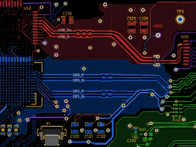
Controlled dielectric focuses on the electrical properties of the substrate material itself. It refers to managing the dielectric constant (Dk) and dissipation factor (Df) across the PCB laminate. Unlike impedance, which is trace-specific, dielectric control is a bulk material requirement. It ensures consistent signal propagation speed and minimizes energy loss.
How Dielectric Properties are Controlled Material suppliers control Dk and Df during the resin formulation and glass fiber weaving process. PCB manufacturers cannot change the inherent Dk of a laminate. Instead, they must source materials from certified suppliers and verify batch consistency. High-frequency applications often require specialized laminates like PTFE, ceramic-filled hydrocarbons, or low-loss FR4 variants. These materials offer stable Dk values and lower signal attenuation than standard epoxy-glass composites.
When Dielectric Control is Required Controlled dielectric is essential for RF circuits, microwave systems, and high-speed analog designs. Applications like radar, satellite communication, and 5G base stations operate at frequencies where standard FR4 exhibits excessive signal loss and phase variation. Buyers must specify the required Dk tolerance and maximum Df value. The manufacturer then sources the appropriate laminate and verifies it meets the electrical specifications.
Key Differences and Decision Factors
The choice between prioritizing impedance control or dielectric control depends on the application frequency, signal type, and performance requirements. The following table helps buyers distinguish the two concepts and align them with project needs.
| Comparison Area | Controlled Impedance | Controlled Dielectric |
|---|---|---|
| Primary Focus | Trace geometry and reference planes | Substrate material electrical properties |
| Control Method | Etching tolerance and stack-up thickness | Laminate selection and supplier certification |
| Key Parameters | Trace width, copper weight, Dk, thickness | Dielectric constant (Dk), Dissipation factor (Df) |
| Typical Tolerance | ±10% (Standard), ±5% / ±3% (High Precision) | ±0.05 Dk, specific Df limits |
| Best For | High-speed digital (USB, HDMI, PCIe), RF | Microwave circuits, 5G, analog phase stability |
| Verification Method | TDR testing on impedance coupons | Material datasheet verification and network analysis |
Design and Manufacturing Considerations
Impedance and dielectric properties interact closely in real-world designs. Buyers and manufacturers must address several engineering challenges to ensure both specifications are met.
Stack-Up Design and Tolerance Stack-Up The dielectric thickness directly impacts impedance. If the prepreg thickness varies beyond tolerance, the impedance will shift even if the trace width is perfect. Manufacturers must review the stack-up carefully and account for resin flow during lamination. For controlled dielectric applications, the Dk variation across the panel must also be considered. High-frequency laminates often have tighter thickness and Dk tolerances than standard materials.
Etching Compensation and Surface Roughness Standard etching processes create trapezoidal trace profiles. This reduces the effective trace width and alters the impedance calculation. Manufacturers apply etching compensation to maintain target values like 50Ω or 100Ω. Additionally, copper surface roughness increases effective Dk and signal loss at high frequencies. For controlled dielectric projects, using low-profile or reverse-treated copper foil helps maintain signal integrity and reduces insertion loss.
Panelization and Material Utilization High-frequency laminates are often more expensive and available in limited sheet sizes. Panelization must optimize material usage while maintaining impedance test coupon placement. Buyers should discuss panelization strategies early to avoid yield loss or unexpected material costs.
Material Selection and Sourcing
Selecting the right material is the foundation of both impedance and dielectric control. Standard FR4 materials offer adequate performance for general digital designs but exhibit Dk variation and high loss at microwave frequencies.
Standard vs. High-Frequency Laminates For controlled impedance digital boards (like USB or Ethernet), standard or mid-loss FR4 materials are usually sufficient. The manufacturer focuses on precise etching and thickness control. For controlled dielectric RF applications, buyers must specify low-loss materials. These laminates provide stable Dk values across temperature and frequency ranges. The High Frequency PCB manufacturing process requires specialized routing tools and handling procedures to prevent material damage.
Supplier Certification and Batch Consistency Material properties can vary between production lots. Buyers working on controlled dielectric projects should require material certificates and batch traceability. Manufacturers must store high-frequency laminates in controlled environments to prevent moisture absorption, which alters Dk and causes delamination during reflow.
Testing and Verification Methods
Verification ensures that the manufactured boards meet the specified electrical requirements. The testing approach differs significantly between impedance and dielectric control.
Time Domain Reflectometry (TDR) for Impedance TDR is the standard method for verifying controlled impedance. The manufacturer includes impedance test coupons on the production panel. A TDR instrument sends a fast rise-time pulse through the coupon trace and measures the reflection. The result shows the actual impedance profile. Buyers should require TDR reports for every production lot, especially for critical interfaces like PCIe or HDMI. Reliable Impedance Controlled PCBs manufacturing always includes this verification step.
Network Analysis for Dielectric Properties Verifying controlled dielectric requires more advanced equipment. Manufacturers use vector network analyzers (VNAs) to measure insertion loss and phase delay on test structures. These tests confirm that the material Dk and Df match the datasheet specifications. For most projects, relying on certified material suppliers and batch documentation is sufficient. Direct dielectric testing is typically reserved for aerospace or defense applications.
Project Preparation Checklist
Preparing accurate specifications prevents miscommunication and ensures the manufacturer applies the correct process controls. Buyers should verify the following items before releasing fabrication files.
- Define target impedance values (e.g., 50Ω, 100Ω) and tolerances (±10% or ±5%)
- Specify reference planes and stack-up requirements clearly
- Select appropriate laminate based on frequency and loss requirements
- Request material certificates and batch traceability for RF designs
- Include impedance test coupons in the fabrication drawing
- Confirm etching compensation and copper roughness requirements
Need Help from the Professionals?
Controlled impedance and controlled dielectric address different signal integrity challenges. Impedance control manages trace geometry and reference paths for high-speed digital signals like USB, HDMI, and PCIe. Dielectric control manages substrate material properties for RF and high-frequency analog circuits. Successful projects require clear specification of both requirements during the design phase.
Buyers should collaborate with the manufacturer early to review the stack-up, material selection, and testing plan. Verifying impedance with TDR coupons and sourcing certified laminates for dielectric stability ensures reliable performance. By aligning design intent with manufacturing capabilities, hardware teams can prevent signal integrity issues and accelerate time to market.
For engineering review and fabrication support, please send your Gerber files and stack-up requirements to sales@toplinecircuit.com.