Open circuits in PCB circuits are a common problem in electronic repair, often directly affecting the normal operation of equipment, such as failure to power on, signal interruption, or functional failure. In actual repair, relying on a single diagnostic method is often insufficient; a comprehensive analysis combining multiple testing methods is necessary. Referring to relevant electronic repair knowledge materials can also help deepen the understanding of PCB structure and fault logic, thereby improving overall repair efficiency and accuracy.

Using Basic Testing Tools to Locate Open Circuits
Before starting testing, a clear approach is needed to avoid blind operation and secondary damage.
- Resistance/Continuity Testing Method: Use a multimeter in buzzer mode to test the continuity of the circuit segment by segment, quickly locating suspected open circuit areas.
- Segmented Troubleshooting Method: Gradually break down the testing range according to the circuit’s functional modules to narrow down the fault location and improve diagnostic efficiency.
This step focuses on the proper use of basic tools. Step-by-step testing can quickly pinpoint the problem area, reducing wasted troubleshooting time.
Determine abnormal lines based on appearance and signal analysis
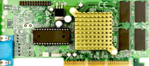
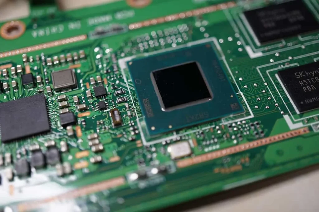
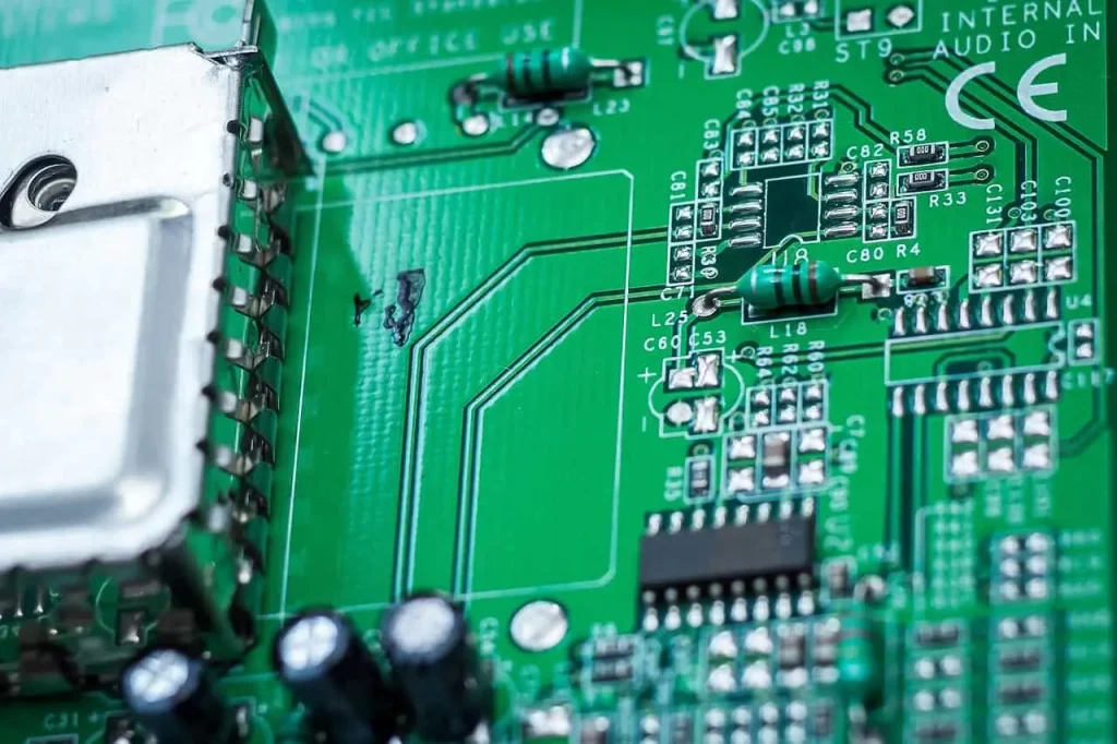
Prior to conducting detailed inspection, observing the surface condition of the PCB is a critical step.
- Visual Inspection: Check for obvious abnormalities such as broken wires, burn marks, corrosion, or detached solder joints.
- Signal Tracing Method: Detect signal transmission point by point while the circuit is powered on to determine the location of the interruption.
Combining visual inspection with signal analysis allows for a more intuitive discovery of potential problems, improving the accuracy and efficiency of diagnosis.
Repairing Different Open Circuit Situations
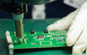
After confirming the location of the open circuit, an appropriate repair method needs to be selected based on the actual damage.
- Thin Wire Jumper Repair: Use a wire to bridge the broken circuit to restore electrical connection.
- Solder Joint Reconstruction: Re-solder areas with poor solder joints or detached solder joints to enhance stability.
This stage focuses on the targeted selection of repair methods. Different types of damage require different treatment methods to ensure stable circuit operation after repair.
Detecting and repairing open circuits on PCB circuits is a process that requires a combination of experience and meticulous operation. From basic measurement to visual judgment and final repair, each step affects the final result. Only by understanding the circuit structure and systematically checking can the repair success rate be improved and the probability of rework reduced. At the same time, continuously accumulating practical experience and learning from relevant technical materials helps to improve the overall repair level, making it more efficient and stable when facing complex PCB faults.